Table of Contents
Advertisement
Quick Links
Advertisement
Table of Contents

Related Manuals for Star Lake SR700-X3

Summary of Contents for Star Lake SR700-X3
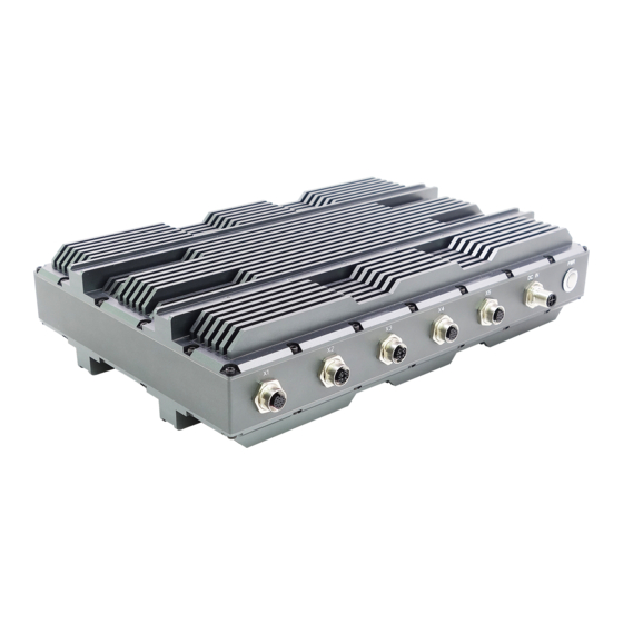
- Page 1 SR700-X3 IP65 MIL-STD-810G Rugged Computer...
-
Page 2: Safety Information
SR700-X3 User’s Manual Safety Information Electrical safety To prevent electrical shock hazard, disconnect the power cable from the electrical outlet before relocating the system. When adding or removing devices to or from the system, ensure that the power cables for the devices are unplugged before the signal cables are connected. -
Page 3: Revision History
SR700-X3 User’s Manual Revision History Revision Date (yyyy/mm/dd) Changes V1.0 2019/10/16 First release V2.0 2020/6/5 Upgrade Motherboard Packing list If any of the above items is damaged or missing, please contact your local distributor. -
Page 4: Table Of Contents
SR700-X3 User’s Manual Table Contents Safety Information ..........................1 Revision History ............................2 Packing list ..............................2 Table Contents ............................. 3 Chapter 1: Product Introduction ......................5 Specifications ........................5 Dimensions ......................... 7 Panel Component ....................... 8 Chapter 2: Connector pin definition ....................... 9 2.1 DC-IN Power Connector………………………………………………………………………………………………..9... - Page 5 3.5.1.1 Graphics Configuration………………………………………………………………………………………….21 3.5.1.2 LCD Control……………………………………………………………………………………………………………22 3.5.2 PCH-IO Configuration……………………………………………………………………………………………….22 3.6 Security……………………………………………………………………………………………………………………….23 3.7 Boot…………………………………………………………………………………………………………………………….23 3.8 Save & Exit…………………………………………………………………………………………………………………..24...
-
Page 6: Chapter 1: Product Introduction
SR700-X3 User’s Manual Chapter 1: Product Introduction 1.1 Specifications System High Power i7-7820EQ Intel® 7th Gen Core™ i7-7820EQ (Frequency 3.0GHz, Turbo Boost Processor Frequency up to 3.7GHz), Quad-Core, 8 Thread Support, 8MB SmartCache. Memory type Up to 32GB DDR4 SDRAM... - Page 7 Physical Dimension 350 x 230 x 86 mm Weight 8.6 Kg ( 18.9 lbs ) Chassis SECC Heatsink Aluminum Alloy, Corrosion Resistant Finish Anodic aluminum oxide ( Color Iron gray ) Cooling Natural Passive Convection/Conduction. No Moving Parts. Connectors DC-IN : Phoenix Contact 1424136 Ethernet : Phoenix Contact 1424177 VGA : Phoenix Contact 1441833 USB : Phoenix Contact 1424177...
-
Page 8: Dimensions
SR700-X3 User’s Manual 1.2 Dimensions... -
Page 9: Panel Component
SR700-X3 User’s Manual 1.3 Panel Component... -
Page 10: Chapter 2: Connector Pin Definition
SR700-X3 User’s Manual Chapter 2: Connector pin definition 2.1 DC-IN Power Connector... -
Page 11: Vga (X4)
SR700-X3 User’s Manual... -
Page 12: Appendix 1. Test Power Cable
SR700-X3 User’s Manual... -
Page 13: Test Vga Cable
SR700-X3 User’s Manual... -
Page 14: Chapter 3: Ami Bios Utility
Chapter 3: AMI BIOS UTILITY This chapter provides users with detailed descriptions on how to set up a basic system configuration through the AMI BIOS setup utility. 3.1 Starting To enter the setup screens, perform the following steps: • Turn on the computer and press the <Del> key immediately. •... -
Page 15: Main Menu
3.3 Main Menu The Main menu is the screen that first displays when BIOS Setup is entered, unless an error has occurred. System Date Use this function to change the system date. Select System Date using the Up and Down <Arrow> keys. Enter the new values through the keyboard. Press the Left and Right <Arrow>... -
Page 16: Cpu Configuration
3.4.1 CPU Configuration 3.4.2 Power & Performance... -
Page 17: Pch-Fw Configuration
3.4.3 PCH-FW Configuration 3.4.4 ACPI Setting... -
Page 18: It8786 Super Io Configuration
3.4.5 IT8786 Super IO Configuration User can choose a mode (RS232/RS422/RS485) on each serial port. -
Page 20: Hardware Monitor
3.4.6 Hardware Monitor... -
Page 21: Csm Configuration
3.4.7 CSM Configuration 3.5 Chipset... -
Page 22: Sa Configuration
3.5.1 SA Configuration 3.5.1.1 Graphics Configuration... -
Page 23: Lcd Control
3.5.1.2 LCD Control Primary IGFX Boot Display: Select the Video Device which will be activated during POST. This has no effect if external graphics present. Secondary boot display selection will appear based on your selection. VGA modes will be supported only on primary display. LCD Panel Type: Select LCD panel used by Internal Graphics Device by selecting the appropriate setup item. -
Page 24: Security
3.6 Security 3.7 Boot... -
Page 25: Save & Exit
Bootup NumLock State: Select the keyboard NumLock state. Quiet Boot: Enables or disables Quiet Boot option. Fast Boot: Enables or disables boot with initialization of a minimal set of devices required to launch active boot option. Has no effect for BBS boot options. Boot option priorities Boot Option #1: Sets the system boot order. - Page 26 This screen provides functions for handling changes made to the BIOS settings and the exiting of the Setup program. Save Changes and Exit Exit system setup after saving the changes. Discard Changes and Exit Exit system setup without saving any changes. Save Changes and Reset Reset the system after saving the changes.
Need help?
Do you have a question about the SR700-X3 and is the answer not in the manual?
Questions and answers