Table of Contents
Advertisement
Quick Links
Introduction
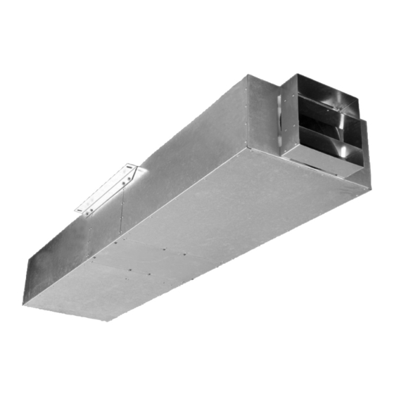
The Nuaire SVT impulse unit comprises a high temperature
axial fan with specially designed inlet and outlet attenuators
which, along with the fan unit, are encased in a Galvanised
steel acoustic enclosure.
Fan Coding Descriptions
SVT
1 (A-E)
1
2
3
1. AXUS Impulse fan
2. Case size
3. Impeller blade angle
The Nuaire SVT unit comprising fan/motor assembly, and
inlet & outlet silencers shall be certified for high temperature
O
operation at 300
C for 2 hours, the range shall have been type
tested to EN12101-3.
The units shall be either 2 speed or inverter driven providing,
low speed for day to day environmental ventilation and one off
operation for emergency ventilation (S1 duty). They shall also
be suitable for reversible operation.
Fully reversible options (i.e similar duty in both airflow
directions) are available, please contact Nuaire for details.
The unit shall have a unique mounting bracket, which shall
enable the bracket to be positioned as a "first fix" component
with the unit being fitted as a "second fix" component, avoiding
possible mechanical damage.
The Nuaire SVT unit shall have inlet guards for safety purposes
and also to prevent debris being sucked through the fan. It also
has a specially designed airflow deflector to direct the jet
stream from the fan at the required angle sufficient to overcome
the natural buoyancy effect of the smoke.
EN12101-3 compliant, refer to EC certificate of conformity
10086-CPD-467873.
Handling
Always handle the units carefully to avoid damage and
distortion. If mechanical aids are used to lift the unit,
spreaders should be employed and
Figure 1.
positioned so as to prevent the
slings, webbing etc. making
contact with the casing.
AXUS SVT
High Temperature Impulse Axial Fans
Installation and Maintenance
Attach SVT unit to
support brackets
positioned
on the ceiling
Nuaire Limited Western Industrial Estate Caerphilly United Kingdom CF83 1NA
Telephone: 029 2085 8200 Facsimile: 029 2088 7033
Email: info@nuaire.co.uk www.nuaire.co.uk
Installation
Installation must be carried out by competent personnel in
accordance with the appropriate authority and conforming
to all statutory governing regulations.
1)
Fixing unit jig and brackets together
Check that you have 2 off support brackets (SVT-BRKT2)
along with the unit jig. Attach the 2 brackets to the jig as
shown below in figure 2.
Figure 2.
Support brackets
attach to jig
2) Fixing support brackets to ceiling
Using the four 30mm x 12mm slots in the top side of the two
brackets attach the jig and support brackets to the ceiling.
3) Remove the jig
Remove the jig so only the support brackets are in position on
the ceiling. (see figure 3).
Figure 3.
673mm
4) Fit main SVT unit to brackets
The SVT unit can now be raised up into position between the
two support brackets on the ceiling and attached when required.
1
o
300
C for 2hr
Unit jig
Support brackets (2 off)
616mm ctrs
602mm
50mm
Figure 4.
Leaflet Number 671256 November 2006
Advertisement
Table of Contents

Related Manuals for NuAire AXUS SVT Series


Summary of Contents for NuAire AXUS SVT Series
- Page 1 “second fix” component, avoiding 616mm ctrs possible mechanical damage. The Nuaire SVT unit shall have inlet guards for safety purposes 673mm 602mm and also to prevent debris being sucked through the fan. It also...
- Page 2 30 minutes to ensure correct operation. If any fault occurs, the equipment should be switched off. Do not re-start until the fault has been rectified. Maintenance General Nuaire recommends all products maintained in accordance with Model Weight the HVCA “Standard Maintenance Specification for Mechanical SVT1...
- Page 3 Operating constraints Enquiries i. Check on the nameplate that the selected motor corresponds Please contact Nuaire Limited for information on any aspects to the maximum exposure temperature and duration. of the motor performance that may need clarification. Contact ii. Non ventilated motors MUST be placed in the airflow from must be made prior to any remedial action being taken under the driven fan.
- Page 4 The equipment referred to in this Declaration of Incorporation is supplied by INSTALLATION REQUIREMENTS Nuaire to be assembled into a ventilation system which may or may not include In addition to the particular requirements given for the individual product, the additional components.
Need help?
Do you have a question about the AXUS SVT Series and is the answer not in the manual?
Questions and answers