Table of Contents
Advertisement
Quick Links
11. Adjustment
Loosen the knobs to adjust
the display to the desired
+5°/-12°
angle and tighten the knobs
to secure.
+ +
- -
+ +
- -
Z
Maintenance
• Check that the bracket is secure and safe to use at regular intervals(at least every three months).
• Please contact your distributor if you have any questions.
1200mm
1250mm
1300mm
1350mm
1400mm
1450mm
1500mm
Display panel center
1550mm
height measured
1600mm
from floor.
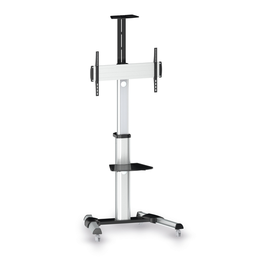
TV Floor Cart and Accessories
200x200
300x300
PDS-0001C
400x200
400x400
600x400
INSTALLATION MANUAL
CAUTION:
DO NOT EXCEED
RATED LISTED WEIGHT. SERIOUS
INJURY OR PROPERTY DAMAGE
MAY OCCUR!
TV
TV
DVD
DVD
CAMERA
CAMERA
70"
50kg
50kg
5kg
5kg
5kg
5kg
MAX
(110lbs)
(110lbs)
(11lbs)
(11lbs)
(11lbs)
(11lbs)
RATED
RATED
RATED
RATED
RATED
RATED
Advertisement
Table of Contents

Related Manuals for PureMounts PDS-0001C


Summary of Contents for PureMounts PDS-0001C
- Page 1 1550mm height measured 1600mm from floor. CAUTION: DO NOT EXCEED RATED LISTED WEIGHT. SERIOUS INJURY OR PROPERTY DAMAGE MAY OCCUR! 200x200 CAMERA CAMERA 300x300 70" PDS-0001C 400x200 50kg 50kg 400x400 (110lbs) (110lbs) (11lbs) (11lbs) (11lbs) (11lbs) Maintenance RATED RATED RATED...
- Page 2 Ensure that you have received all parts according to the component checklist prior to installation. If any parts are missing or faulty, telephone your local distributor for a replacement. PDS-0001C WARNING • Do not begin the installation until you have read and understood all the instructions and warnings contained in this installation sheet.
- Page 3 1. Assembling the Base • Insert the right leg into the base. Align the holes in the right leg to the holes in the base. Secure with the screws. Repeat this step for the left leg. • Each castor can be adjusted independently for fine tuning. Slightly turn the nut to lower or raise the base. 2.
- Page 4 3. Installing the Support Plate Attach the support plate to the column with the screws. Tighten all screws using a suitable screwdriver. 4. Installing the Adapter Brackets Insert the washers into the back of universal plate along the plate rails. Attach the two plastic covers to both ends of the plate using the appropriate screws.
- Page 5 5. Hooking the Display onto the Support Plate 4-1 For Flat Back Screens M-A/M-B/M-C · Hook the universal plate onto the support plate. · Tighten two screws to secure them. 4-2 For Recessed Back Screens or to Access A/V Inputs IMPORTANT: Make sure the display is mounted correctly and that the screws are tightened safely before releasing the display.
- Page 6 9. Installing the Connecting Plate 7. Cable Management Attach the connecting plate to the column at the desired height using appropriate screws. Tighten all screws using a suitable screwdriver. 10. Display Orientation 8. Installing the Camera Shelf A: For Landscape View Attach the camera shelf to the B: For Portrait View connecting plate using...
Need help?
Do you have a question about the PDS-0001C and is the answer not in the manual?
Questions and answers