Table of Contents
Advertisement
Quick Links
Advertisement
Table of Contents

Subscribe to Our Youtube Channel
Related Manuals for SLOPE INDICATOR GTecLink

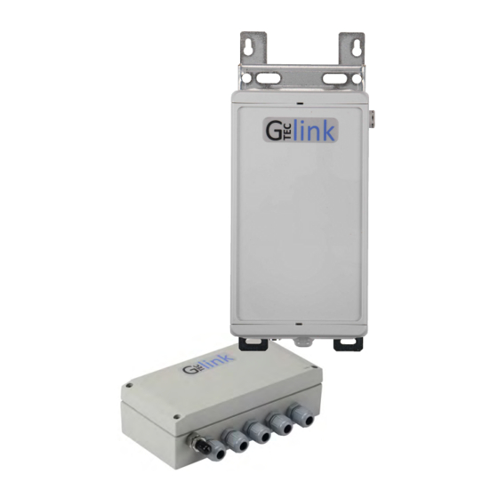
Summary of Contents for SLOPE INDICATOR GTecLink
- Page 1 GTecLink Dataloggers Manual...
-
Page 2: Table Of Contents
1.2 Powering the data logger 1.3 Safely closing the data logger 1.4 Data logger mounting Datalogger Configuration 2.1 STEP 1: Connect GTecLink Android application 2.2 STEP 2: GTecLink main menu 2.4 STEP 3: Sensor configuration Vibrating Wire Nodes (526160xx) GeoFlex Nodes (5780170x) Analog Node (57804800) 2.5 STEP 4: Sensors Data... - Page 3 GTecLink Datalogger Manual 3.2.1 Sensor Connection 3.2.2 Battery lifespan a) Geosense / RST IPI b) Sisgeo IPI c) MDT Multi-Point-Borehole-Extensometers (MPBX) 3.2.3 Configuration 3.2.4 Data storage 3.3 Analog Logger 3.3.1 Sensor Connection 3.3.2 Battery lifespan 3.3.3 Configuration 3.3.4 Data storage 4.
-
Page 4: About This Document
DGSI and powered by Loadsensing. Further technical description is available in the datasheets. The family of GTecLink data loggers by DGSI consists of six different dataloggers that may be used as standalone data loggers (without remote communication) or radio dataloggers (with remote communication through a gateway). -
Page 5: Datalogger Installation
GTecLink Datalogger Manual 1. DATA LOGGER INSTALLATION 1.1 Equipment GTecLink dataloggers are shipped with the following accessories: Datalogger Antenna Antenna adapter RTC battery (if applicable) Not included: USB-OTG configuration cable Batteries Sensor surge protection Grounding protection Mounting supports (if needed) -
Page 6: Powering The Data Logger
GTecLink Datalogger Manual 1.2 Powering the data logger The data logger arrives closed and without batteries installed. In order to initialize it, the user should follow these steps: Open the datalogger (using a 2.5 mm Allen wrench) following the recommended positions (Figure 1) in order to avoid damaging the lateral gore valve. The batteries are inserted into the cover, so be careful not to snap the cable between the cover and the main board. - Page 7 GTecLink Datalogger Manual The RTC battery keeps time in the data logger regardless of whether or not C-type batteries are also inserted. The data logger always uses UTC time. However, the data can be visualized in local time in the ...
- Page 8 GTecLink Datalogger Manual 1.3 Sensor connection Sensors are connected to the datalogger at the terminal blocks. Each terminal block corresponds to one channel of the data logger. The terminal blocks accept wires that are prepared by stripping a short length of insulation from the end. ...
-
Page 9: Safely Closing The Datalogger
2.5 N.m. The GTecLink family of data loggers by DGSI have undergone watertightness testing by an external laboratory and is rated IPX7 (1 meter for 30 minutes) and IPX8 for extended immersion (1 meter for 7 days). ... - Page 10 GTecLink Datalogger Manual ● The cable glands are closed with a 19 mm open spanner (e.g. Bahco 19 mm Single Ended Open Spanner; RS Amidata code 717-8992) and the internal nut is held with a 22 mm open spanner (e.g.
-
Page 11: Datalogger Mounting
Even though the dataloggers are IP67 certified, we recommend installing them in holes with proper drainage so that they won’t be permanently covered with All GTecLink dataloggers are protected against lightning and there is an easy-to-use grounding screw (Figure 4) next to the cable glands, which may be connected to provide protection. -
Page 12: Datalogger Configuration
(Battery usage may be required as Android devices may not be able to power some sensors.) The GTecLink app starts up once the device has been connected to the datalogger using the USB-OTG cable. Manual startup is not necessary. ... -
Page 13: Step 1: Connect Gteclink Android Application
GTecLink Datalogger Manual 2.1 STEP 1: Connect GTecLink Android application Download the app onto your Android device from the DGSI website: https://durhamgeo.com/downloads/android/gteclink.apk Connect your device to the node using the USB-OTG cable (Accessories list). Make sure the node is powered on (BATT mode). The app will automatically appear and display the node’s basic information. -
Page 14: Step 2: Gteclink Main Menu
GTecLink Datalogger Manual 2.2 STEP 2: GTecLink main menu 1) Node info: Basic information about the node (version, ID, temperature, etc.). 2) Sensors data: Access to real time sensor readings and downloaded data stored in the node. 3) Node Configuration: A ccess this menu to configure the node. -
Page 15: Step 3: Sensor Configuration
Slot time chapters in the Gateway User Guide. Each type of GTecLink datalogger has its own sensor configuration parameters. For more information about the configuration of each sensor, go to the corresponding datalogger section. Once the nodes are connected, we strongly recommend setting the sampling rate again from the gateway in order to optimize the radio configuration of the network. ... -
Page 16: Geoflex Nodes (5780170X)
GTecLink Datalogger Manual GeoFlex Nodes Choose the GeoFlex communication protocol among the options available. Select Auto Setup . T h e resulting reading file will create a column for each address. Analog Node This data logger is compatible with seven types of analog sensors: voltage, Full Wheatstone Bridge, Thermistor, Current loop, potentiometer, DGSI In-Place Inclinometers and PT100. ... -
Page 17: Step 4: Sensors Data
Advanced Options: Default configuration parameters should be suitable for the majority of networks. See the Radio specification chapter of the Gateway User Guide or Annex 01: GTecLink Gateway Radio Specifications v1.8 for more details on radio models and settings. Bear in mind that the GTecLink app saves and maintains Radio settings ... - Page 18 GTecLink Datalogger Manual The network size is the number of nodes (data loggers and GTecLink wireless sensors). We strongly recommend initially setting it to the final number of nodes that the wireless network will have since this parameter determines the available sampling rates. Bigger networks do not allow selection of small sampling rates. ...
-
Page 19: Step 6: Radio Signal Coverage Test
Quality of the signal received by the gateway from the data logger. By clicking the “Next” button, GTecLink will run an O nline test. For the results of this test to be immediately displayed on the Android device, the gateway and the Android device must also be connected to the Internet. ... - Page 20 GTecLink Datalogger Manual If the Android does not have an active Internet connection, then the test must be run offline. Click on “Offline test”. A CSV file with the test results can be downloaded from the gateway web interface. ...
-
Page 21: Step 7: Test Results Interpretation
GTecLink Datalogger Manual 2.8 STEP 7: Test results interpretation The results displayed are listed for each Spreading Factor (SF). The SF represents a way of modulating data. The lower the SF number is, the shorter the message; thus, more messages can be sent on the network. ... -
Page 22: Gteclink Dataloggers
After each terminal block is connected, we recommend taking a sensor reading in order to ensure that the connections have been carried out correctly. This reading should be compared with the sensor reading at installation with a portable readout unit before connecting to the GTecLink datalogger. Note that some configuration is required during installation. ... -
Page 23: Barometric Measurements
GTecLink Datalogger Manual 3.1.2 Barometric measurements The data logger includes a barometer (BOSCH BMP180 device). It is important to avoid placing the data logger inside any type of container. This would affect correct readings by the barometer through the gore valve. ... -
Page 24: Configuration
GTecLink Datalogger Manual NOTE: Extreme temperatures could cut down the capacity by 20 to 40%, Check battery specifications. USB not used. 3.1.4 Configuration The vibrating wire node requires configuration of the sweep frequency before starting. There are several existing predefined sweep frequencies: ... -
Page 25: Geoflex Loggers
GTecLink Datalogger Manual 3.2 GeoFlex Dataloggers 3.2.1 Sensor Connection LS-G6-DIG data logger supports different sensor models by default (RS485 port): ● DGSI GeoFlex In-Place Inclinometers https://durhamgeo.com/product/geoflex/ ● Geosense Inclinometer ● RST inclinometer ● Sisgeo inclinometer ● MDT’s Multi-Point Borehole extensometer (MPBX) The GeoFlex datalogger can power and read 10 GeoFlex sensors with the standard configuration (57801705). - Page 26 GTecLink Datalogger Manual Figure 47: View of the inside of the GeoFlex data logger connected to a GeoFlex string; b)RST inclinometer; c) Sisgeo inclinometer, placing a resistor between A and B is recommended according to the manufacturer’s specs. d) MDT Multi Point Borehole Extensometer (MBPX) ...
-
Page 27: Battery Lifespan
GTecLink Datalogger Manual GeoFlex data loggers (Figure 47) can also support other digital sensors with SDI interface connections. These types of sensors are not supported by default by the data logger, but drivers can be developed by Worldsensing engineers. Please contact DGSI Tech Support to discuss additional sensor types and to obtain a quote for the driver development. -
Page 28: C) Mdt Multi-Point-Borehole-Extensometers (Mpbx)
GTecLink Datalogger Manual c) MDT Multi-Point-Borehole-Extensometers (MPBX) Table 6: Indicative lifespan for GeoFlex datalogger. Estimates using 4 C-size cells Sampling rate Number 30 of sensors 1 hour 5 minutes 1 minute minutes 1 (RS485) > 7 years 6 years ... -
Page 29: Data Storage
GTecLink Datalogger Manual 3.2.4 Data storage The datalogger has capacity for up to 90,000 readings from the inclinometers, which are two-axis inclinometers with temperature variation calibration, grouped by 5 sensors. Is also has capacity for up to 90,000 readings for MPBX, grouped by 5 sensors (of 6 anchors). (Table 6). ... -
Page 30: Analog Logger
GTecLink Datalogger Manual 3.3 Analog Datalogger 3.3.1 Sensor Connection The Analog datalogger supports seven different sensor models that can be connected independently to four different channels (Figure 48): ● Voltage (+/- 10 V peak to peak) ● Full Wheatstone Bridge (39.06 mV) ●... - Page 31 GTecLink Datalogger Manual Figure 50: View of the wiring of different types of analog sensors, indicated in the Android Configuration App. The datalogger can measure both voltage differential and single ended voltage sensor outputs. The standard wiring is for differential. For single ended, it is necessary to wire the negative input of the data logger to the datalogger ground. ...
-
Page 32: Battery Lifespan
GTecLink Datalogger Manual 3.3.2 Battery lifespan The following tables provide the indicative battery lifespan for the Analog datalogger, (Table 7 a, b and c) depending on the type of sensor, the warm up time and the sampling rate. Bear in mind that consumption varies depending on the sensor used, sampling rate and environmental conditions. - Page 33 GTecLink Datalogger Manual b) Sensor features Channels & sampling Voltage Voltage Voltage Voltage @12V@24mA @12V@24mA @24V@24mA @24V@24mA Warm up time 1 second 5 seconds 1 second 5 seconds 1 CH 5 min 5 months 2.5 months...
- Page 34 GTecLink Datalogger Manual c) Sensor features Channels Potentiome & FWB@5V FWB@5V@ Potentiometer Thermistor@5V ter@5V@1.5 PT100 sampling @0.7 kΩ 1.4 kΩ @5V@5 kΩ @3 kΩ kΩ 1 CH 5 1.5 1.5 years 1.5 years 1.5 years ...
-
Page 35: Configuration 3.3.4 Data
GTecLink Datalogger Manual 3.3.3 Configuration Configuration requires specifying the excitation power voltage and the warm up time for the sensors that need power supply (voltage and current loop sensors). For other sensors, 5V excitation supply is present in all channel connectors. -
Page 36: Data Acquisition
The Android device allows these CSV files to be opened with downloaded applications such as e-mail or cloud apps. Files are also stored on the device memory, on the SD Card, in the GTecLink folder. G TecLink application: Readings dump to the Android device. -
Page 37: Contact Dgsi
GTecLink Datalogger Manual 5. CONTACT Durham Geo Slope Indicator Phone : +1 425 588 0858 (12.00h - 24.00h UTC) Technical support : s upport@dgsi.zendesk.com General information : i nfo@dgeslope.com Durham Geo Slope Indicator 2175 West Park Court ...
Need help?
Do you have a question about the GTecLink and is the answer not in the manual?
Questions and answers