Advertisement
Quick Links
Installation instructions
KNX SA 4MDC.8 AP
Keep for future use!
Valid from 1st March 2017
General information
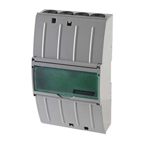
Fig. 1
KNX SA 4MDC.8 AP
The KNX SA 4MDC.8 AP sun shading actuator is a device
for the central operation of up to four sun shading drives
24 V DC pole changer switching with 8 push button
inputs.
The device is operated using a KNX bus system. The
sun shading actuator and the drives are supplied with
24 V DC.
Intended use
The KNX SA 4MDC.8 AP was developed to control sun
shading products. The approval of the manufacturer
must be obtained for any use of the device other than its
intended purpose specified in these instructions.
Safety instructions
WARNING
The electrical installation must be per-
formed by a certified electrician in ac-
cordance with the electrical installation
regulations published by the Association
of German Electrical Engineers (VDE
0100) or the standards and legal require-
ments of the country in which the device
is being installed. The electrician must
observe the installation instructions inclu-
ded with the supplied electrical devices.
WARNING
If hazard-free operation cannot be assu-
med, the device may not be started or
must be deactivated. This assumption is
justified if:
t he housing or the connecting lines show
signs of damage,
the device is no longer working.
2016159_0•en•2017_03_01
WARNING
It is important to comply with the fol-
lowing points in the interest of personal
safety.
Children may not play with the operating elements of
the control unit or the remote control. Store remote
controls out of reach of children.
Make sure that no persons or objects are in the range
of movement of the driven parts (blinds, external vene-
tian blinds, etc.).
Disconnect the device from the operating voltage if
cleaning or other maintenance work must be perfor-
med.
Function of the sun shading actuator
You will find a detailed description of the software func-
tions for the KNX sun shading actuators in the manual
(art. no. 2014 788). You can download the manual and
the product database of the sun shading actuator from
www.warema.com.
Installation
AP: Insert a slotted screwdriver (recommendation: 3.0 - 4.0
mm blade) into a cover opening (Fig. 3) and carefully
pry open the hinged cover. Repeat the procedure for the
second opening of the cover. After both latches have been
unlatched,
the cover can be removed. Open the second cover in
the same way. Alternatively, the AP model may also be
mounted on a DIN rail (TH 35-15 in accordance with EN
60715: 2001).
Electrical connection
An on-site overload current protection device (fuse) and a
disconnecting and isolating switch to switch off the entire
system must be provided.
The electrical connection is made as shown in the wiring
diagram on the reverse side (Fig. 4), the connection to
the KNX bus system and the drives is made using spring
terminals, the connecting lines are designed as screw
terminals.
We reserve the right to make technical changes
1
Advertisement

Related Manuals for WAREMA KNX SA 4MDC.8 AP


Summary of Contents for WAREMA KNX SA 4MDC.8 AP
- Page 1 Installation instructions KNX SA 4MDC.8 AP Keep for future use! Valid from 1st March 2017 General information WARNING It is important to comply with the fol- lowing points in the interest of personal safety. Children may not play with the operating elements of the control unit or the remote control.
- Page 2 This software ends the programming mode After starting the app, the surrounding area is scanned for automatically. The red LED goes out. WAREMA sun shading actuators. Available actuators are shown and can be operated. If the programming mode is to be ended earlier, press the programming button again.
- Page 3 Voltage V DC 106 mm 180 mm Conformity can be viewed at www.warema.com This device complies with the EMC directives for use in residential and commercial areas. Inputs on local operating elements (sunblind push buttons, 3 ‒ 4 mm 1-pin) and signal inputs...
- Page 4 Motor 1 Motor 2 Motor 3 Motor 4 24 V DC 24 V DC 24 V DC 24 V DC 2 x 0.75 mm ² 2 x 0.75 mm ² ATTENTION: The operating voltage must be SELV voltage in accordance with VDE 0700-1 or EN 60335-1.
Need help?
Do you have a question about the KNX SA 4MDC.8 AP and is the answer not in the manual?
Questions and answers