Table of Contents
Advertisement
Quick Links
Advertisement
Table of Contents

Related Manuals for Tenma 72-14120


Summary of Contents for Tenma 72-14120
- Page 1 Function Generator Model 72-14120, 72-14122 and 72-14126...
-
Page 2: Table Of Contents
Contents ..................................... 1 Safety Terms and Symbols ..........................3 1.2 General Safety Overview ..........................4 Chapter 2 .................................... 5 Brief Introduction of Tenma Series Function/Arbitrary Waveform Generator ............. 5 Main Characteristics ............................5 Introduction of Panels and Keys ........................6 2.2.1 Front Panel ............................ - Page 3 4.2.5 Select Trigger Source ........................100 4.2.6 Trigger Output ..........................101 4.2.7 Trigger Edge ..........................101 4.2.8 Comprehensive Example ....................... 102 4.3 Output Burst ..............................105 4.3.1 Select Burst ........................... 105 4.3.2 Type of Burst ..........................107 4.3.3 Phase of Burst ..........................109 4.3.4 Period of Burst ..........................
-
Page 4: Safety Terms And Symbols
Chapter 1 Safety Information 1.1 Safety Terms and Symbols Terms in the manual The following terms may appear in the manual: Warning: warning statement, pointing out conditions and behaviors that may endanger life safety. Caution: cautionary statement, pointing out conditions and behaviors that may cause damage to the product and other properties. -
Page 5: General Safety Overview
1.2 General Safety Overview • This instrument is designed and manufactured in compliance with: G84793, lEC61010-1, CAT III 600V, Pollution Degree 2 and Double Insulation standards. • When using electrical appliances basic safety precautions should always be followed. • Check that the voltage indicated on the rating plate corresponds with that of the local network before connecting the appliance to the mains power supply. -
Page 6: Chapter 2
Chapter 2 Brief Introduction of Tenma Series Function/Arbitrary Waveform Generator Function/arbitrary waveform generator of the series uses direct digital synthesis to generate accurate and stable waveform output with resolution as low as 1μHz as an economic, high-performance and multi-functional dual-channel function/ arbitrary waveform generator. -
Page 7: Introduction Of Panels And Keys
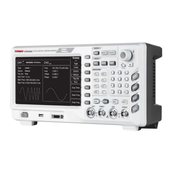
2.2 Introduction of Panels and Keys 2.2.1 Front Panel Function/arbitrary waveform generator provides users with simple and intuitive front panel that is easy to operate, which is shown in Figure 2-1: User’s key/digital Quick selection interface/frequency of waveform type meter/modulation/sweep Soft function Page Up/Down Display... - Page 8 3. Protocol interface Interface supporting RS232, I2C and SPI protocols and any 16bit digital arbitrary wave is capable of corresponding communication protocol output, and used with DIGITAL menu. 4.CH1 output terminal/ sync output terminal Waveform signal and synchronous signal output of channel 1. Switching of output signal is controlled by CH1 or submenu under UTILITY.
- Page 9 12.Direction key Switch numerical digits or move (left or right) cursor when setting parameters with multi-functional control and direction key. The left key can be used to clear the last digit input when inputting using the data keys. 13. Multi-functional control/key Rotate the multi-functional control to change the number (increase the number by clockwise rotation) or select menu key.
-
Page 10: Back Panel
2.2.2 Back Panel Back panel is shown in Figure 2-2: Heat emission Crate lock grille AC power input Internal socket 10MHz output terminal External 10M Mains power Hz input on/off switch terminal Frequency meter LAN port External analog External digital interface modulation input interface... -
Page 11: Function Interface
6.External analog modulation input terminal In modulation of AM, FM, PM, SUM or PWM signal is external, input modulation signal is received through external analog modulation input terminal. The corresponding modulation depth, frequency deviation, phase deviation or duty ratio deviation is controlled by ±5V signal level of the external analog modulation input terminal. 7.USB interface Connect to the external computer software through this USB interface to initialise control of the instrument by computer. - Page 12 Detailed description: CH1 information: highlighted display (red illumination) means that this part of display screen displays information about channel 1. Parameters of this channel can be set. Parameters of this channel cannot be set if not highlighted. Press CH1 to enable. Output (highlighted “ON” means that channel output is turned on, and highlighted “OFF” means that channel output is turned off), output impedance (“HighZ”...
-
Page 13: Chapter 3 Quick Start
Chapter 3 Quick Start 3.1 Output Basic Waveform 3.1.1 Set Output Frequency The default configuration of waveform is a sine wave with frequency of 1kHz and peak-to-peak amplitude of 100mV (terminating at 50Ω) when powering on. For example the specific steps for changing frequency into 2.5MHz are as follows: 1. - Page 14 2. Input the required number 2.5 with numeric keyboard. The left direction key can be used to backspace when inputting. Figure 3- 2 Set frequency 3. Select required unit. Press soft key of corresponding unit. The waveform generator outputs waveform with the displayed frequency when you select unit and output is switched on.
-
Page 15: Set Output Amplitude
3.1.2 Set Output Amplitude The default configuration of waveform is a sine wave with peak-to-peak amplitude of 100mV (terminating at 50Ω) when powering on. The specific steps for changing amplitude into 300mV pp are as follows: 1. Press function key F2 until the required soft key border outline illuminates to match the colour of the corresponding channel and character “Amp”... -
Page 16: Set Dc Offset Voltage
3.1.3 Set DC Offset Voltage The default configuration of waveform is a sine wave with DC offset voltage of 0V (terminating at 50Ω) when powering on. The specific steps for changing DC offset voltage into -150mV are as follows: 1. Press function key F3 until the required soft key border outline illuminates to match the colour of the corresponding channel. -
Page 17: Set Square Wave
3.1.4 Set Square Wave The duty ratio of square wave represents time quantum of square wave at high level in each cycle (suppose waveform is not reversed). The default duty ratio of square wave is 50% when powering on. The duty ratio is restricted by minimum pulse width specification 10ns. -
Page 18: Set Pulse Wave
50% when powering on. Rising/falling edge time of 72-14126 is 5ns (72-14122 is 6ns/ 72-14120 is 7ns). The specific steps for setting pulse wave with period of 2ms, amplitude of 1.5Vpp, DC offset of 0V, duty ratio (restricted by minimum pulse width specification 10ns) of 25%, rising edge time of 200µs and falling edge time of... -
Page 19: Set Dc Voltage
3.1.6 Set DC Voltage Output of DC voltage is setting of the above-mentioned DC offset. The default DC voltage is initially 0V when powering on. The specific steps for changing DC offset voltage into 3V are as follows: 1. Press DC followed by Offset to enter the setting. 2. -
Page 20: Set Sawtooth Wave
3.1.7 Set Sawtooth Wave Degree of symmetry is time quantum when slope of sawtooth wave is positive in each cycle (if waveform is not reversed). The default degree of symmetry of sawtooth wave is 0.10% when powering on. The specific steps for setting triangular wave with frequency of 10kHz, amplitude of 2V, DC offset of 0V and degree of symmetry of 50% are as follows: Press Ramp, Freq, Amp, Offset and Symmetry in sequence. -
Page 21: Set Noise Wave
3.1.8 Set Noise Wave Quasi-Gaussian noise with amplitude of 100mVpp and DC offset of 0mV is default in the function/arbitrary waveform generator. If the amplitude and DC offset function of other waveforms are changed, the default value of noise wave will also be changed. -
Page 22: Sync Output
3.2 SYNC Output The two SYNC connectors on the front panel provide SYNC output. All standard waveform outputs (except DC and noise) are equipped with associated Sync output. Sync output of each corresponding channel can be turned off in UTILITY option. -
Page 23: Frequency Measurement
3.3 Frequency Measurement This function/arbitrary waveform generator can measure frequency and duty ratio of compatible TTL level signal. The range of frequency measurement is 100mHz~200MHz. When frequency meter is used, signal of compatible TTL level is input through external frequency meter interface (Counter connector). Press COUNTER to read “frequency”, “period”, “duty ratio”, “positive pulse width”... -
Page 24: Chapter 4 Advanced Applications
Chapter 4 Advanced Applications 4.1 Output Modulation Waveform 4.1.1 Amplitude Modulation (AM) In amplitude modulation, the modulated waveform generally is composed of carrier wave and modulation wave. The amplitude of carrier wave will vary with that of modulation wave. The modulation mode of the two channels is mutually independent. - Page 25 Carrier frequency range varies with carrier waveform. The default frequency of all carrier waves is 1kHz. See the table below for frequency range of carrier wave: Table 4- 1 Frequency Carrier waveform 72-14120 72-14122 72-14126 1μHz~ 80MHz 1μHz ~ 120MHz 1μHz ~ 160MHz Sine wave 1μHz ~ 30MHz...
- Page 26 Figure 4- 3 Select modulation source Internal source In case of internal modulation source, modulation wave can be sine wave, square wave, sawtooth wave and arbitrary wave, and is sine wave by default. After you use AM function, modulation wave is sine wave by default. You can change it with multi-functional control on AM interface or by pressing Wave.
- Page 27 Set modulation depth Modulation depth is the degree of amplitude change, expressed in percentage. The range of AM depth is 0%~120%, 100% by default. When modulation depth is 0%, a constant amplitude is output (half of carrier amplitude). When modulation depth is 100%, the output amplitude varies with the modulation waveform. When modulation depth is more than 100%, the instrument will not output a peak-to-peak voltage (terminating at 50Ω) more than ±5V.
- Page 28 Figure 4- 5 Set modulation parameters Press the corresponding soft key, input the required value and select the unit. Figure 4- 6 Set frequency of modulation source 3) Set carrier signal parameters Select type of basic waveform in modulation mode. Press Square to select the carrier signal as a square wave.
- Page 29 Figure 4- 7 Set carrier frequency You can set with multi-functional control and direction key, or press corresponding soft keys of function again. Figure 4- 8 Select carrier duty ratio To set some parameters, press the corresponding soft key, input the required value and select the unit.
- Page 30 Figure 4- 9 Set carrier duty ratio Set modulation depth Press soft key Return to return to the interface below to set modulation depth after setting the carrier parameters. Figure 4- 10 Select modulation depth You can set with multi-functional control and direction key. You can also press the soft key Depth again, input number 80 through numeric keyboard and press soft key % to set the modulation depth.
- Page 31 Figure 4- 11 Set modulation depth Use channel output Press CH1 on the front panel to turn on output of channel 1. The backlight of CH1 illuminates after channel output is turned on, “ON” on the right of CH1 information tag turns white, and “OFF” is greyed out, indicating that the output of channel 1 is turned on.
-
Page 32: Frequency Modulation(Fm
Check the shape of AM modulation waveform through oscilloscope, which is shown in the figure below: Figure 4- 13 Observe AM waveform with oscilloscope 4.1.2 Frequency Modulation(FM) In frequency modulation, the modulated waveform generally is composed of a carrier wave and modulation wave. The frequency of the carrier wave will vary with amplitude of the modulation wave. - Page 33 Carrier frequency range varies with carrier waveform. The default frequency of all carrier waves is 1kHz. See the table below for frequency range of carrier wave: Table 4- 2 Frequency Carrier Waveform 72-14120 72-14122 72-14126 1μHz~ 80MHz 1μHz ~ 120MHz 1μHz ~ 160MHz...
- Page 34 Figure 4- 16 Select modulation source Internal source In case of internal modulation source, modulation wave can be sine wave, square wave, sawtooth wave and arbitrary wave, and is sine wave by default. After you use FM function, the modulation wave is sine wave by default. You can change it with multi-functional control on interface for using frequency modulation or by pressing the relevant key for basic waveform setting.
- Page 35 Set frequency deviation Frequency deviation is the deviation of frequency of waveform subject to FM from the carrier frequency. The range of FM frequency deviation is 1μHz to half of the maximum carrier frequency, 1kHz by default. You can change it with the multi-functional control and direction key on the interface for using frequency modulation or by pressing Freq.
- Page 36 Figure 4- 18 Set modulation parameters To set some parameter, press corresponding soft key, input the required value and select the unit. Figure 4- 19 Set frequency of modulation source Set carrier signal parameters Press Sine to select carrier signal as a sine wave if previously set to another mode. (Default carrier signal is a sine wave).
- Page 37 Figure 4- 20 Set carrier frequency You can input settings using the multi-functional control and direction key. Press corresponding soft key, input the required value and select the unit. Figure 4- 21 Set carrier amplitude Set frequency deviation Press MOD to return to the interface below to set the frequency deviation after setting carrier parameters.
- Page 38 Figure 4- 22 Return to FM setting You can input settings using the multi-functional control and direction key. You can also press Freq Dev again, input number 5 through numeric keyboard and press soft key kHz to set the frequency deviation. Figure 4- 23 Set frequency deviation Use channel output Press CH1 on the front panel to turn on output of channel 1.
-
Page 39: Phase Modulation(Pm
Figure 4- 24 Use channel output Check the shape of FM modulation waveform through oscilloscope, which is shown in the figure below: Figure 4- 25 Observe waveform with oscilloscope 4.1.3 Phase Modulation(PM) In phase modulation, the modulated waveform generally is composed of carrier wave and modulation wave. The phase of the carrier wave will vary with amplitude of the modulation wave. - Page 40 Figure 4- 26 Select PM function Select carrier waveform The PM carrier waveform can be sine wave, square wave, sawtooth wave or arbitrary wave (except DC), and is sine wave by default. After PM is selected, press the key of basic waveform setting to enter the interface for setting carrier wave. Figure 4- 27 Select carrier waveform Set carrier frequency Carrier frequency range varies with carrier waveform.
- Page 41 Table 4- 3 Frequency Carrier waveform 72-14120 72-14122 72-14126 1μHz~ 80MHz 1μHz ~ 120MHz 1μHz ~ 160MHz Sine wave 1μHz ~ 30MHz 1μHz ~ 40MHz 1μHz ~ 50MHz Square wave 1μHz ~ 30MHz 1μHz ~ 40MHz 1μHz ~ 50MHz Sawtooth wave 1μHz ~ 2MHz...
- Page 42 External source When using an external modulation source, modulation wave and frequency will not show in the parameter list, when an external waveform will be used to modulate carrier waveform. Phase deviation of PM is controlled by ±5V signal level on external analog modulation input terminal (Modulation In connector) on the back panel.
- Page 43 Set modulation signal parameters Set with the multi-functional control and direction keys after using the PM function. You can also press the corresponding soft keys of function on the above interface for using PM function, when the screen shown below will display. Press the corresponding soft key, input the required value and select the unit.
- Page 44 You can also set with the multi-functional control and direction keys. You can also press corresponding soft keys of function again, when the interface below will display. To set some parameter, press corresponding soft key, input the required value and select the unit. Figure 4- 32 Set carrier amplitude Set phase deviation Press MOD to return to the interface below to set phase deviation after setting carrier parameters.
- Page 45 You can set with the multi-functional control and direction keys. You can also press soft key Phase Dev again, input number 200 through the numeric keyboard and press soft key º to set the phase deviation. Figure 4- 34 Set phase deviation Use channel output Press CH1 on the front panel to turn on output of channel 1.
-
Page 46: Amplitude Shift Keying(Ask
Check the shape of PM modulation waveform through the oscilloscope, which is shown in the figure below: Figure 4- 36 Observe PM waveform with oscilloscope 4.1.4 Amplitude Shift Keying(ASK) In amplitude shift keying, ASK expresses digital signals “0” and “1” by changing amplitude of carrier signal and outputs carrier signals with different amplitude according to logic of modulation signal. - Page 47 Carrier frequency range varies with carrier waveform. The default frequency of all carrier waves is 1kHz. See the table below for frequency range of carrier wave: Table 4- 4 Frequency Carrier waveform 72-14120 72-14122 72-14126 1μHz~ 80MHz 1μHz ~ 120MHz 1μHz ~ 160MHz Sine wave 1μHz ~ 30MHz...
- Page 48 Select modulation source The function/arbitrary waveform generator can select an internal or external modulation source. After you use ASK function, the modulation source is internal by default. You can change it with multi-functional control on interface for using amplitude shift keying function or by pressing Source. Figure 4- 39 Select modulation source Internal source When using an internal modulation source, the modulation wave can be sine wave, square wave, sawtooth wave and...
- Page 49 Comprehensive example First set the instrument to run in ASK mode, and then set an internal logic signal of 300Hz as modulation signal and a sine wave with frequency of 15kHz and amplitude of 2Vpp as carrier signal. The specific steps are as follows: Note: only the frequency of this signal can be set.
- Page 50 Figure 4- 41 Set carrier parameters You can also set with the multi-functional control and direction keys. You can also press the corresponding soft keys of function again, when the interface below will display. To set the parameter, press corresponding soft key, input the required value and select the unit.
- Page 51 Figure 4- 43 Set ASK rate You can also set with the multi-functional control and direction keys. You can also press soft function key Freq again, input number 300 through the numeric keyboard and press soft key Hz to set the ASK rate. Figure 4- 44 Set ASK rate Use channel output Press CH1 on the front panel to turn on output of channel 1.
-
Page 52: Frequency Shift Keying(Fsk
Figure 4- 45 Use channel output Check the shape of the ASK modulation waveform through oscilloscope, which is shown in the figure below: Figure 4- 46 Observe ASK waveform with oscilloscope 4.1.5 Frequency Shift Keying(FSK) The function/arbitrary waveform generator can move between two preset frequency (carrier frequency and hopping frequency) in frequency shift keying. - Page 53 Figure 4- 47 Select FSK function Select carrier waveform FSK carrier waveform can be sine wave, square wave, sawtooth wave or arbitrary wave (except DC), and is sine wave by default. After FSK modulation is selected, press the key of basic waveform setting to select carrier waveform. Figure 4- 48 Select carrier waveform Set carrier frequency Carrier frequency range varies with carrier waveform.
- Page 54 Table 4- 5 Frequency Carrier waveform 72-14120 72-14122 72-14126 1μHz~ 80MHz 1μHz ~ 120MHz 1μHz ~ 160MHz Sine wave 1μHz ~ 30MHz 1μHz ~ 40MHz 1μHz ~ 50MHz Square wave 1μHz ~ 30MHz 1μHz ~ 40MHz 1μHz ~ 50MHz Sawtooth wave 1μHz ~ 2MHz...
- Page 55 FSK function or by pressing Hop Freq. The range of hopping frequency depends on the carrier waveform. See the table below for frequency range of carrier wave: Table 4- 6 Frequency Carrier waveform 72-14120 72-14122 72-14126 1μHz~ 80MHz 1μHz ~ 120MHz 1μHz ~ 160MHz...
- Page 56 Figure 4- 50 Select FSK function Set carrier signal parameters Press Sine to select carrier signal as a sine wave if previously set to another mode (Default carrier signal is a sine wave) when FSK modulation signal is on. You can also set with the multi-functional control and direction keys. You can also press corresponding soft keys of function again, when the interface below will display.
- Page 57 Figure 4- 52 Set modulation amplitude You can set with the multi-functional control and direction keys directly on this interface. You can also press the corresponding soft keys of function again, when the interface below will display. Press the corresponding soft key, input the required value and select the unit.
-
Page 58: Phase Shift Keying (Psk)
Figure 4- 54 Use channel output Check the shape of FSK modulation waveform through the oscilloscope, which is shown in the figure below: Figure 4- 55 Observe FSK waveform with oscilloscope 4.1.6 Phase Shift Keying (PSK) The function/arbitrary waveform generator can move between two preset phases (carrier phase and modulation phase) in phase shift keying. - Page 59 Figure 4- 56 Select PSK function Select carrier waveform PSK carrier waveform can be sine wave, square wave, sawtooth wave or arbitrary wave (except DC), and is sine wave by default. After PSK modulation is selected, press the key of basic waveform setting to select carrier waveform. Figure 4- 57 Select carrier waveform Set carrier frequency Carrier frequency range varies with carrier waveform.
- Page 60 Table 4- 7 Frequency Carrier waveform 72-14120 72-14122 72-14126 1μHz~ 80MHz 1μHz ~ 120MHz 1μHz ~ 160MHz Sine wave 1μHz ~ 30MHz 1μHz ~ 40MHz 1μHz ~ 50MHz Square wave 1μHz ~ 30MHz 1μHz ~ 40MHz 1μHz ~ 50MHz Sawtooth wave 1μHz ~ 2MHz...
- Page 61 External source When using an external modulation source, the rate will not show in the parameter list, when an external waveform will be used to modulate carrier waveform. PSK output phase is determined by logic level on external digital modulation interface (FSK Trig connector).
- Page 62 Figure 4- 60 Set modulation parameters Set PSK rate and modulation phase Press MOD to return to the interface below after setting carrier parameters: Figure 4- 61 Set modulation parameters You can set with the multi-functional control and direction keys directly on this interface. You can also press the corresponding soft keys of function again, when the interface below will display.
-
Page 63: Binary Phase Shift Keying(Bpsk
Figure 4- 62 Use channel output Check the shape of PSK modulation waveform through oscilloscope, which is shown in the figure below: Figure 4- 63 Observe PSK waveform with oscilloscope 4.1.7 Binary Phase Shift Keying(BPSK) The function/arbitrary waveform generator can move between two preset phases (carrier phase and modulation phase) in binary phase shift keying, expressing 0 and 1. - Page 64 Figure 4- 64 Select BPSK function Select carrier waveform BPSK carrier waveform can be sine wave, square wave, sawtooth wave or arbitrary wave (except DC), and is sine wave by default. After PSK modulation is selected, press the key of basic waveform setting to select carrier waveform. Figure 4- 65 Select carrier waveform Set carrier frequency Carrier frequency range varies with carrier waveform.
- Page 65 Table 4- 8 Frequency Carrier waveform 72-14120 72-14122 72-14126 1μHz~ 80MHz 1μHz ~ 120MHz 1μHz ~ 160MHz Sine wave 1μHz ~ 30MHz 1μHz ~ 40MHz 1μHz ~ 50MHz Square wave 1μHz ~ 30MHz 1μHz ~ 40MHz 1μHz ~ 50MHz Sawtooth wave 1μHz ~ 2MHz...
- Page 66 External source When using an external modulation source, rate will not show in the parameter list, when an external waveform will be used to modulate carrier waveform. BPSK output phase is determined by logic level on external digital modulation interface (FSK Trig connector). For example, when external input logic is low, carrier phase is output; when external input logic is high, modulation phase is output.
- Page 67 Set carrier signal parameters Press Sine to select carrier signal as a sine wave if previously set to another mode (Default carrier signal is a sine wave). You can set with the multi-functional control and direction keys. You can also press corresponding soft keys of function again, when the interface below will display.
- Page 68 You can set with the multi-functional control and direction keys directly on this interface. You can also press the corresponding soft keys of function again, when the interface below will display. To set the parameters, press corresponding soft key, input the required value and select the unit. Figure 4- 70 Set modulation rate Use channel output Press CH1 on the front panel to turn on output of channel 1.
-
Page 69: Quadrature Phase Shift Keying(Qpsk
Check the shape of BPSK modulation waveform through oscilloscope, which is shown in the figure below: Figure 4- 72 Observe BPSK waveform with oscilloscope 4.1.8 Quadrature Phase Shift Keying(QPSK) The function/arbitrary waveform generator can move between four preset phases (carrier phase and 3 modulation phases) in QPSK. - Page 70 Carrier frequency range varies with carrier waveform. The default frequency of all carrier waves is 1kHz. See the table below for frequency range of carrier wave: Table 4- 9 Frequency Carrier waveform 72-14120 72-14122 72-14126 1μHz~ 80MHz 1μHz ~ 120MHz 1μHz ~ 160MHz...
- Page 71 Figure 4- 75 Select modulation source Set QPSK rate The frequency between carrier phase and modulation phase can be set. After you use QPSK function, you can set QPSK rate, which is in the range of 2mHz~1MHz and 10kHz by default. You can change it with multi-functional control and direction key on the interface for using PSK function or by pressing Rate.
- Page 72 Figure 4- 76 Select QPSK function Set carrier signal parameters Press Sine to select carrier signal as a sine wave if previously set to another mode (Default carrier signal is a sine wave). You can set with the multi-functional control and direction keys. You can also press the corresponding soft keys of function again, when the interface below will display.
- Page 73 Figure 4- 78 Set QPSK parameters You can set with the multi-functional control and direction keys directly on this interface. You can also press the corresponding soft keys of function again, when the interface below will display. To set some parameter, press corresponding soft key, input the required value and select the unit.
-
Page 74: Oscillation Keying(Osk
Figure 4- 80 Use channel output Check the shape of QPSK modulation waveform through oscilloscope, which is shown in the figure below: Figure 4- 81 Observe QPSK waveform with oscilloscope 4.1.9 Oscillation Keying(OSK) The function/arbitrary waveform generator can output a sinusoidal signal of intermittent oscillation in OSK. Carrier waveform is output when internal crystal oscillator starts oscillation;... - Page 75 Set carrier frequency The default frequency of carrier wave is 1kHz. See the table below for frequency range of carrier wave: Table 4- 10 Frequency Carrier waveform 72-14120 72-14122 72-14126 1μHz~ 80MHz 1μHz ~ 120MHz 1μHz ~ 160MHz Sine wave...
- Page 76 To set carrier frequency, please use the multi-functional control and direction keys or press soft key Freq, input the required value and select the unit. Select modulation source The function/arbitrary waveform generator can select internal or external modulation source. After you use PSK function, the modulation source is internal by default.
- Page 77 OSK function Press MOD, Type and OSK successively (press soft key Type to select ) to use OSK function. Figure 4- 85 Select OSK function Set carrier signal parameters Press Sine to select carrier signal as a sine wave if previously set to another mode (Default carrier signal is a sine wave). You can set with the multi-functional control and direction keys.
- Page 78 Set OSK rate, modulation phase and PN code Press MOD to return to the interface below after setting carrier parameters: Figure 4- 87 Set modulation parameters You can set with the multi-functional control and direction keys directly on this interface. You can also press the corresponding soft keys of function again, when the interface below will display.
-
Page 79: Quadrature Amplitude Modulation(Qam
Figure 4- 89 Use channel output Check the shape of OSK modulation waveform through the oscilloscope, which is shown in the figure below: Figure 4- 90 Observe OSK waveform with oscilloscope 4.1.10 Quadrature Amplitude Modulation(QAM) In QAM, two signals of the same frequency but with phase difference of 90° are used as carrier wave, which is subject to amplitude modulation with baseband signal. - Page 80 Select QAM Press MOD, Type and QAM in sequence to use QAM function (if “Type” is not highlighted, press soft key Type to select). After QAM function is used, the function/arbitrary waveform generator will output modulated waveform with the current carrier phase (0º...
- Page 81 Set carrier frequency Table 4- 11 Carrier Frequency waveform 72-14120 72-14122 72-14126 1μHz~ 80MHz 1μHz ~ 120MHz 1μHz ~ 160MHz Sine wave To set carrier frequency, use the multi-functional control and direction keys or press soft key Freq, input the required value and select the unit after selecting carrier waveform.
- Page 82 Figure 4- 94 Set carrier parameters Set QAM modulation mode, PN code and modulation rate Press MOD to return to the interface below after setting carrier parameters: Figure 4- 95 Set modulation parameters You can set with the multi-functional control and direction keys directly on this interface. You can also press the corresponding soft keys of function again, when the interface below will display.
- Page 83 Figure 4- 96 Set modulation rate Use channel output Press CH1 on the front panel to turn on output of channel 1. The backlight of CH1 illuminates after channel output is turned on, “ON” to the right of CH1 information tag turns white, and “OFF” is greyed out, indicating that the output of channel 1 is turned on.
-
Page 84: Sum Modulation(Sum
Check the shape of QAM modulation waveform through oscilloscope, which is shown in the figure below: Figure 4- 98 Observe QAM waveform with oscilloscope 4.1.11 Sum Modulation(SUM) In SUM, the modulated waveform generally is composed of carrier wave and modulation wave. The output waveform is obtained by the sum of product of carrier amplitude and modulation factor and product of amplitude of modulation wave and modulation factor. - Page 85 Carrier frequency range varies with carrier waveform. The default frequency of all carrier waves is 1kHz. See the table below for frequency range of carrier wave: Table 4- 12 Frequency Carrier waveform 72-14120 72-14122 72-14126 1μHz~ 80MHz 1μHz ~ 120MHz 1μHz ~ 160MHz...
- Page 86 Figure 4- 100 Select modulation source Internal source When using an internal modulation source, modulation wave can be sine wave, square wave, ascending sawtooth wave, descent sawtooth wave, arbitrary wave and noise, and is sine wave by default. After you use SUM function, the modulation wave is sine wave by default.
- Page 87 Set modulation depth Modulation depth is the degree of amplitude change, expressed as a percentage. The range of SUM depth is 0%~100%, 100% by default. When modulation depth is 0%, carrier wave is output. When modulation depth is 100%, modulation wave is output.
- Page 88 Figure 4- 102 Set modulation parameters Set carrier signal parameters Select type of basic waveform in modulation mode. Press Square to select the carrier signal as a square wave. Figure 4- 103 Set carrier parameters You can set with the multi-functional control and direction keys. You can also press the corresponding soft keys of function again.
- Page 89 Figure 4- 104 Set carrier duty ratio Set modulation depth Press soft key MOD to return to the interface below to set the modulation depth after setting carrier parameters. You can set with the multi-functional control and direction keys. You can also press soft key Depth again, input the number 80 through the numeric keyboard and press soft key % to set the modulation depth.
-
Page 90: Pulse Width Modulation(Pwm
Check the shape of SQUARE modulation waveform through oscilloscope, which is shown in the figure below: Figure 4- 106 Use channel output 4.1.12 Pulse Width Modulation(PWM) In PWM, the modulated waveform generally is composed of carrier wave and modulation wave. The pulse width of carrier wave will vary with the amplitude of modulation wave. - Page 91 Carrier waveform PWM carrier waveform can only be pulse wave. After PWM is selected, press Pulse to enter interface of carrier waveform. Figure 4- 108 Set carrier waveform Set carrier frequency The frequency range of pulse wave is 1μH~50MHz. Default frequency is 1kHz. To set carrier frequency, please use the multi-functional control and direction keys in the interface or press soft function key Freq, input the required value and select the unit.
- Page 92 Figure 4- 109 Select modulation source Internal source When using an internal modulation source, the modulation wave can be sine wave, square wave, ascending sawtooth wave, descent sawtooth wave, arbitrary wave and noise, and is sine wave by default. After you use PWM function, the modulation wave is sine wave by default.
- Page 93 Comprehensive example First set the instrument to run in PWM mode, and then set an internal sine wave of 1kHz as modulation signal and a pulse wave with frequency of 10kHz, amplitude of 2Vpp, duty ratio of 50% and rising/falling time of 100ns as carrier signal. Finally set duty ratio deviation to be 40%.
- Page 94 Figure 4 - 111 Set modulation parameters Set carrier signal parameters Press soft function key Pulse to enter the interface for setting carrier parameters in the interface for using PWM function. Figure 4 - 112 Set carrier parameters You can set with the multi-functional control and direction keys. You can also press the corresponding soft keys of function again, when the interface below will display.
- Page 95 Figure 4- 113 Set rising edge Set duty ratio deviation Press Pulse to return to the interface below to set frequency deviation after setting carrier parameters. Figure 4- 114 Set modulation parameters You can set with the multi-functional control and direction keys. You can also press the soft function key Duty again, input the number 40 through the numeric keyboard and press soft key % to set the duty ratio deviation.
- Page 96 Figure 4- 115 Set duty ratio deviation Use channel output Press CH1 on the front panel to turn on output of channel 1. The backlight of CH1 illuminates after channel output is turned on, “ON” to the right of CH1 information tag turns white, and “OFF” is greyed out, indicating that the output of channel 1 is turned on.
-
Page 97: Output Frequency Sweep Waveform
Check the shape of PWM modulation waveform through oscilloscope, which is shown in the figure below: Figure 4- 117 Observe PWM waveform with oscilloscope 4.2 Output Frequency Sweep Waveform When selecting frequency sweep mode, the output frequency of function/arbitrary waveform generator changes in a linear or logarithmic way from starting frequency to stop frequency in designated frequency sweep time. -
Page 98: Set Starting And Stop Frequency
Figure 4- 118 Select SWEEP function Select frequency sweep waveform After frequency sweep is started, press the key of basic waveform setting to select frequency sweep waveform. For example, select square wave as frequency sweep. Press Square and SWEEP. The interface is shown in the figure below: Figure 4- 119 Select frequency sweep waveform 4.2.2 Set Starting and Stop Frequency... -
Page 99: Frequency Sweep Mode
By default, starting frequency is 1kHz and stop frequency is 1MHz, but the range of starting and stop frequency can vary with frequency sweep waveform. See the table below for the frequency range of frequency sweep wave: Table 4- 13 Frequency Carrier waveform 72-14120 72-14122 72-14126 1μHz~ 80MHz 1μHz ~ 120MHz 1μHz ~ 160MHz... -
Page 100: Frequency Sweep Time
Figure 4- 121 Select linear frequency sweep Figure 4- 122 Select logarithmic frequency sweep 4.2.4 Frequency Sweep Time Set the time from starting frequency to stop frequency, which is 1ms by default and in the range of 1µs~500s. To change it, you can use the multi-functional control and direction keys on the interface for selecting frequency sweep mode or press soft function key Swp Time, input number through the numeric keyboard and press the corresponding soft key of unit. -
Page 101: Select Trigger Source
Figure 4- 123 Set frequency sweep time 4.2.5 Select Trigger Source The signal generator generates frequency sweep output upon receiving a trigger signal and then waits for the next trigger signal. The trigger source of frequency sweep can be internal, external or manual. To change it, you can use the multi-functional control and direction keys on the interface for selecting frequency sweep mode or press the soft function key Source. -
Page 102: Trigger Output
Note: in the event of an external trigger source, trigger output will not be shown in the parameter list, as trigger output is also achieved through external digital modulation interface (FSK Trig connector). This interface cannot be simultaneously used as external trigger input and internal trigger output. Figure 4- 125 Select external trigger source When using manual trigger, the backlight of Trigger on the front panel flashes. -
Page 103: Comprehensive Example
4.2.8 Comprehensive Example First set the instrument to run in frequency sweep mode, and then set a square wave signal with amplitude of 1Vpp and duty ratio of 50% as frequency sweep wave. The frequency sweep mode is linear. Set starting frequency to be 1kHz, stop frequency to be 50kHz and frequency sweep time to be 2ms. - Page 104 You can set the amplitude with the multi-functional control and direction keys. You can also press the corresponding soft function keys again, when the interface below will display. To set the parameters, press the corresponding soft key, input the required value and select the unit. Figure 4- 128 Set waveform amplitude Set starting/stop frequency, frequency sweep time, trigger source and edge.
- Page 105 Figure 4- 130 Set trigger frequency Use channel output Press CH1 on the front panel to turn on output of channel 1. The backlight of CH1 illuminates after channel output is turned on, “ON” to the right of CH1 information tag turns white, and “OFF” is greyed out, indicating that the output of channel 1 is turned on.
-
Page 106: Output Burst
Figure 4- 132 Observe frequency sweep waveform with oscilloscope 4.3 Output Burst Signal generator can create a waveform with designated recurring number (known as pulse train). The function/arbitrary waveform generator supports control of pulse train output with internal, external or manual trigger, and three types of pulse train, including N cycle, gating and infinite. - Page 107 Note: waveform frequency is different with period of pulse train that designates interval between pulse trains (only for N cycle mode). The default frequency of waveform is 1kHz. See the table below for the range: Table 4- 14 Frequency Carrier waveform 72-14120 72-14122 72-14126 1μHz~ 80MHz 1μHz ~ 120MHz 1μHz ~ 160MHz...
-
Page 108: Type Of Burst
4.3.2 Type of Burst The function/arbitrary waveform generator can output three types of pulse train, N cycle, gating and infinite. The default type is N cycle. N cycle mode Press soft keys Type and N Cyc in sequence on the interface for starting pulse function to enter N cycle mode. In this mode, the waveform generator will output a waveform with designated recurring number (pulse train) upon receiving trigger. - Page 109 Figure 4- 136 Select gating mode Infinite mode Press soft function keys Type and Infinite in sequence on the interface for starting pulse function to enter infinite mode. In mode of infinite pulse train, burst period (period of pulse train) and recurring number will not be shown in the parameter list. Infinite pulse train amounts to infinite cycle index of waveform.
-
Page 110: Phase Of Burst
4.3.3 Phase of Burst Phase of pulse train is phase at starting point of pulse train. It is in the range of -360°~+360°. The default initial phase is 0°. To change it, you can use the multi-functional control and direction keys on the interface for selecting type of pulse train or press soft function key Phase. -
Page 111: Select Trigger Source
4.3.6 Select Trigger Source The signal generator generates output of pulse train upon receiving a trigger signal, and then waits for the next trigger signal. The trigger source of pulse train can be internal, external or manual. To change it, you can use the multi-functional control and direction keys on the interface for selecting the type of pulse train or press soft key Source. - Page 112 Figure 4- 139 Set N cycle function Select waveform of Burst After setting N-cycle mode of pulse train, press Sine to select carrier signal as a sine wave if previously set to another mode (Default carrier signal is a sine wave). Figure 4- 140 Select waveform of pulse train You can set amplitude with multi-functional control and direction key (note: if frequency is displayed, only frequency can be set, which means that conversion between frequency and period cannot be realized.
- Page 113 Figure 4- 141 Set waveform amplitude Set period of pulse train and recurring number of waveform Press soft function key BURST to return to the interface below after selecting waveform of pulse train and relevant parameters: Figure 4- 142 Set pulse train parameters You can set with the multi-functional control and direction keys.
- Page 114 Figure 4- 143 Set period of pulse train Use channel output Press CH1 on the front panel to turn on output of channel 1. The backlight of CH1 illuminates after channel output is turned on, “ON” to the right of CH1 information tag turns white, and “OFF” is greyed out, indicating that the output of channel 1 is turned on.
-
Page 115: Output Arbitrary Wave
Check the shape of pulse train through oscilloscope, which is shown in the figure below: Figure 4- 145 Observe BURST waveform with oscilloscope 4.4 Output Arbitrary Wave The function/arbitrary waveform generator stores 160 types of standard waveform in nonvolatile storage. See Table 4-1 (list of built-in arbitrary wave) for the name of waveform. -
Page 116: Point-By-Point Output/Play Mode
Figure 4- 146 Select Arb function 4.4.2 Point-by-point Output/Play Mode The function/arbitrary waveform generator supports point-by-point output of arbitrary waveform. In point-by-point output mode, the signal generator automatically calculates frequency of output signal (476.837158203Hz) according to waveform length (e.g. 1,048,576 points) and sampling rate. The signal generator outputs waveform points one by one with this frequency. -
Page 117: Select Arbitrary Wave
4.4.3 Select Arbitrary Wave The function/arbitrary waveform generator allows users to output arbitrary waveform in internal or external storage of the instrument. You can select the arbitrary wave you need with the multi-functional control and direction keys on the interface for using arbitrary wave function or by pressing soft keys Arb and Wave in sequence. - Page 118 Discharge Discharge curve of NI-MH battery Pahcur Current waveform of brushless DC motor Quake Seismic wave Radar Radar signal Ripple Power ripple RoundHalf Hemispheric wave RoundsPM RoundsPM waveform StepResp Step response signal SwingOsc Swing oscillation function- time curve TV signal Voice Voice signal Airy...
- Page 119 Sectioned amplitude modulation wave of sine Sectioned frequency modulation wave of sine SectMod Sectioned frequency modulation wave of pulse (5types) Sectioned phase modulation wave of sine Sectioned frequency modulation wave of pulse width Cardiac Electrocardiosignal Electro-oculogram Electroencephalogram Bioelect (6 types) Electromyogram Pulseilogram Pulsilogram of common people...
- Page 120 CosH Hyperbolic cosine CosInt Cosine integral Cotangent function CotHCon Concave hyperbolic cotangent CotHPro Convex hyperbolic cotangent CscCon Concave cosecant CscPro Convex cosecant CotH Hyperbolic cotangent CscHCon Concave hyperbolic cosecant Trigonometric CscHPro Convex hyperbolic cosecant function RecipCon Concave reciprocal Trigonome RecipPro Convex reciprocal (21 types) SecCon...
-
Page 121: Create And Edit Arbitrary Waveform
Bartlett Bartlett window BarthannWin Corrected Bartlett window Blackman Blackman window BlackmanH BlackmanH window BohmanWin BohmanWin window Boxcar Rectangular window ChebWin Chebyshev window GaussWin Gaussian window Window Function FlattopWin Flat-top window (17 types) Hamming Hamming window Hanning Hanning window Kaiser Kaiser window NuttallWin Minimum four-item Blackman-Harris window ParzenWin... -
Page 122: Description Of Interface Front Panel
4.5.1 Description of Interface Front Panel Digital interface of front panel is shown in the figure below: 数字接口 Digital interface 连接插头 Connecting plug 分接头1 分接头2 Tap 1 Tap 2 、 See the table below for correspondence of signal Table 4- 16 Pin name Function description Ground pin... -
Page 123: Uart Protocol
4.5.2 UART Protocol The function/arbitrary waveform generator can generate serial port protocol signal for parameters and output through the digital interface on the front panel in UART protocol mode. Select UART Press DIGITAL, Type and Uart in sequence to use UART function (if “Type” is not highlighted, press soft key Type to select). - Page 124 Figure 4- 149 Select Baud rate Set Bit Different bit number can be set as required. In UART mode, there are five different modes, 4, 5, 6, 7 and 8. The default is 4. To set Baud rate, please use the multi-functional control and direction keys after selecting protocol or press the soft function key Bit Type to select the required setting.
- Page 125 Figure 4- 151 Set data sent Multibyte sending can be set. The number of bytes is 8. The numeric string should be divided into digital sections not more than 255 when setting value sent. Segments are separated by a Space. Press Clear to clear input errors and press A/a to switch between upper and lower case.
- Page 126 Set sending mode Automatic and manual sending can be set. In automatic sending mode, the instrument sends the set protocol coding at preset times and in manual mode, the instrument sends the set protocol signal when users press the send key. Automatic sending mode Press soft function key SendMode to adjust to “AUTO”...
- Page 127 Set stop bit Different stop bit width can be set in UART protocol. Press the soft function key Stop Bit to set optional stop bit width, which can be 1 or 2 and is 1 set by default. Figure 4- 155 Set stop bit Set check bit Check mode can be set in UART protocol.
- Page 128 Comprehensive example First set the instrument to run in UART mode, and then set Baud rate of the instrument to be 4800, data to be decimal 5, 20, 13 or 14, check to be odd, stop bit to be 1 and sending interval to be 2ms. The specific steps are as follows: Use UART function Press DIGITAL, Type and Uart in sequence (press soft key “Type”...
- Page 129 Set bit To set the Baud rate, please use the multi-functional control and direction keys after selecting the protocol or press soft function key Bit Type to select the required setting. The bit number shown is 8 in this example. Figure 4- 159 Select bit Set data sent Press the soft function key Data for data setting in UART mode.
- Page 130 Set send time Press the soft function key Send Mode to set the sending mode to “AUTO” in UART mode. Press soft function key Send Time to set the sending interval to be 2ms set using the numeric keys. Figure 4- 161 Set send time Set stop bit Press the soft function key Stop Bit to set the sending mode and set the stop bit to be 1 in UART mode.
-
Page 131: I2C Protocol
Set check bit Press the soft function key Parity to set the check bit to be “Odd” in UART mode. Figure 4- 163 Set check bit 4.5.3 I2C Protocol The function/arbitrary waveform generator can generate protocol signal for parameters and output through the digital interface on the front panel in I2C protocol mode. - Page 132 Set Clock The transmitter Clock of the I2C can be set. You can set with the multi-functional control and direction keys after selecting a protocol or by pressing the soft function key Clock and using the numeric keys in the range of 10kHz~1MHz. Figure 4- 165 Set clock Set address information Different address information can be set as required.
- Page 133 To set the address value, please press the soft function key Addr and use the numeric keys after selecting a protocol. Figure 4- 167 Set address information Set data sent The function/arbitrary waveform generator can set protocol data coding to be sent. After you use I2C function, the data is empty by default.
- Page 134 Set sending mode Automatic and manual sending can be set. When set to automatic sending, the instrument sends the set protocol coding at a certain time.; In manual mode, the instrument sends the set protocol signal when users press the send key. Automatic sending mode Press soft function key SendMode and adjust to “AUTO”...
- Page 135 Comprehensive example First setup the instrument run in I2C mode, and then set address of the instrument to be 10-bit, value to be 65, I2C clock signal to be 500Hz, data to be decimal 17, 19, 23 29 or 31 and sending interval to be 5ms. The specific steps are as follows: Use I2C function Press DIGITAL, Type and I2C in sequence (press soft key “Type”...
- Page 136 Press the soft function key Addr to set the address. Set address information with numeric keyboard after pressing this key to set address value to be 65. Figure 4- 172 Set address value Set Clock Press the soft function key Clock for data setting in I2C mode. You can set with multi-functional control and direction key. You can also press the corresponding soft function keys again and set corresponding data to be 500 with numeric keys.
- Page 137 Set data sent Press the soft function key Data for data setting in I2C mode. You can set with the multi-functional control and direction keys. You can also press the corresponding soft function keys again and set corresponding data with numeric keys. Figure 4- 174 Set data sent Set send time Press the soft function key Send Mode to set sending mode to be “AUTO”...
-
Page 138: Spi Protocol
4.5.4 SPI Protocol The function/arbitrary waveform generator can generate SPI protocol signal for parameters and output through the digital interface on the front panel in SPI protocol mode. Select SPI Press DIGITAL, Type and SPI successively to use SPI function (if “Type” is not highlighted, press soft key Type to select). After SPI function is used, the function/arbitrary waveform generator will output protocol signal with the current SPI mode. - Page 139 Set data sent Different bit number can be set as required. Set with the multi-functional control and direction keys after selecting protocol or by pressing soft function key Data and using the numeric keys. The data can be sent with multiple numerical systems, including decimal system, hexadecimal system and character, which is shown in the figure below.
- Page 140 Set sending mode Automatic and manual sending can be set. In automatic sending mode the instrument sends the set protocol coding in certain time.In manual mode, the instrument sends the set protocol signal when users press the send key. Automatic sending mode Press the soft function key SendMode to adjust to “AUTO”...
- Page 141 Comprehensive example First setup the instrument run in SPI mode, and then set output data of the instrument to be decimal 13, 21, 34, 55 or 89, clock to be 15kHz and sending interval to be 5ms. The specific steps are as follows: Use SPI function Press DIGITAL, Type and SPI in sequence (press soft key “Type”...
- Page 142 Set data sent Press the soft function key Data for data setting in SPI mode. You can set with the multi-functional control and direction key. You can also press the corresponding soft function keys again to set corresponding data with numeric key. Figure 4- 184 Set data sent Set send time Press soft function key Send Mode to set sending mode to be “AUTO”...
-
Page 143: Function Of Digital Arbitrary Wave
4.6 Function of Digital Arbitrary Wave The function /arbitrary waveform generator can generate any digital signal and corresponding clock signal for parameters and output through digital interface of front panel in mode of digital arbitrary wave Select digital arbitrary wave Press DIGITAL, Type and DArb in sequence to use function of digital arbitrary wave (if “Type”... - Page 144 Set data sent Different bit number can be set as required. Set with the multi-functional control and direction keys after selecting protocol or by pressing the soft function key Data and using the numeric keys. The data can be sent with multiple numerical systems, including decimal system, hexadecimal system and character, which is shown in the figure below.
- Page 145 Set sending mode Automatic and manual sending can be set. In the automatic sending mode, the instrument sends the set protocol coding in certain time. In manual mode, the instrument sends the set protocol signal when users press the send key. Automatic sending mode Press the soft function key SendMode to adjust to “AUTO”...
- Page 146 Comprehensive example First make the instrument run in mode of digital arbitrary wave, and then set output data of the instrument to be decimal 27, 131, 9 or 31. The specific steps are as follows: Use function of digital arbitrary wave Press DIGITAL, Type and DArb in sequence (press the soft key “Type”...
- Page 147 Set data sent Press the soft function key Data for data setting in mode of digital arbitrary wave. You can set with the multi-functional control and direction keys. You can also press the corresponding soft function keys again and set corresponding data with numeric keys.
-
Page 148: Chapter 5 Fault Handling
Chapter 5 Fault Handling Possible faults in the use of the function/arbitrary waveform generator and troubleshooting methods are listed below. If these faults occur, please follow the corresponding steps. If they cannot be corrected, please contact the supplier, and provide the information about your machine (method: press Utility and System in sequence). No Display on Screen (Blank Screen) If the signal generator still does not display after pressing power switch on front panel 1) Check that the mains lead is connected and mains power is turned on. -
Page 149: Chapter 6 Service And Support
Chapter 6 Service and Support Program Upgrade of Product Users may upgrade the current firmware available from the support department or website of UNI-T to ensure that the latest revision released by UNI-T is used. -
Page 150: Appendix A: Factory Reset State
Appendix A: Factory Reset State Parameter Factory default Channel parameter Current carrier wave Sine wave 50Ω Output load Sync output Channel 1 Channel output Channel output opposition Amplitude limit Upper amplitude limit Lower amplitude limit Fundamental wave Frequency 1kHz Amplitude 100mVpp DC offset Initial phase... - Page 151 FM modulation Modulation source Internal Modulation wave Sine wave Modulation frequency 100Hz Frequency deviation 1kHz PM modulation Modulation source Internal Modulation wave Sine wave Modulation frequency 100Hz Phase deviation 180° PWM modulation Modulation source Internal Modulation wave Pulse wave Modulation frequency 100Hz Deviation of duty ratio ASK modulation...
- Page 152 BPSK modulation Carrier wave Sine Modulation source Internal Phase 0° Phase 1 90° Coding mode PN15 BPSK rate 10kHz QPSK modulation Carrier wave Sine Modulation source Internal Coding mode PN15 QPSK rate 10kHz Phase 0° Phase 1 90° Phase 2 180°...
- Page 153 Frequency sweep Type of frequency sweep Linear Initial frequency 1kHz Stop frequency 2kHz Frequency sweep time Trigger source Internal Trigger output Trigger edge Rising edge Pulse train Mode of pulse train N cycle Initial phase 0° Burst period (period of pulse train) 10ms Recurring number Gated polarity...
- Page 154 I2C protocol Clock 100Hz Address Data None Sending mode Automatic Send time Address bit width 7bits SPI protocol Clock 1MHz Data None Sending mode Automatic Send time DARB Clock 1KHz Data None Sending mode Automatic System parameter IP type DHCP Clock source Internal Clock output...
-
Page 155: Appendix B: Performance Index
Appendix B: Performance Index Model 72-14120 72-14122 72-14126 Basic characteristic Number of channels Channels A/B with equivalent performance Waveform characteristic 7 types of standard waveform, not less than 160 types of built-in arbitrary waveform Sine( sine wave), Square( square wave), Ramp(ramp wave), Harmonic(harmonic),... - Page 156 Characteristic of pulse signal 1μHz ~ 30MHz 1μHz ~ 40MHz 1μHz ~ 50MHz Frequency range Pulse width Maximum period 2000s:minimum 10ns Variable edge 7ns~10s 6ns~10s 5ns~10s Overshoot < 2% Shake 1ns + 100ppm of period Characteristic of arbitrary wave 1μHz~20MHz 1μHz~30MHz 1μHz~40MHz Frequency range...
- Page 157 FM modulation Carrier wave Sine wave, square wave, sawtooth wave, arbitrary wave Source Internal/external Modulation wave Sine wave, square wave, sawtooth wave, noise, arbitrary wave(1μHz~200kHz) Frequency deviation DC ~ 40MHz DC ~ 60MHz DC ~ 80MHz PM modulation Carrier wave Sine wave, square wave, sawtooth wave, arbitrary wave Source Internal/external...
- Page 158 Modulation wave Sine wave, square wave, upper ramp wave, lower ramp wave, noise, arbitrary wave 2mHz ~ 100kHz (internal);DC ~ 20kHz (external) Modulation frequency SUM depth 0%~100% QAM4,QAM8,QAM16,QAM32,QAM64,QAM128,QAM256(built-in constellation QAM mode modulation) Modulation source Built-in PNcode,PN7,PN9,PN11,PN15,PN17,PN21,PN23,PN25 Chip rate 2mHz~100kHz 10mVpp~10Vpp(50Ω) Amplitude Frequency sweep Carrier wave...
- Page 159 interval Stop bit 1 bit,2 bits Check bit No check bit, odd, even Output level TTL level output DARB Waveform length 1~1K bytes Sampling rate 1S/s ~ 40MS/s Sending mode Single manual trigger, continuous trigger(no time interval) Waveform resolution Maximum 16 bits Output level TTL level output Modulation input...
- Page 160 High frequency High frequency noise suppression is turned on or off suppression Adjustable trigger 0% ~ 100.0% sensitivity Coupled mode DC, AC Interface USB Host(maximum 32G), USB Device, LAN, Standard configuration 10MHz clock source input, 10MHz clock source output Power source Supply voltage 100~240VACrms,45~440Hz,CAT II 300V Power consumption...
-
Page 161: Appendix C: List Of Accessories
Appendix C: List of Accessories Model AWG series (dual channel) Mains power lead for country supplied USB data line Standard configuration Two BNC cables (1m) CD for users LAN port Optional components Digital interface, digital cable... -
Page 162: Appendix D: Maintenance And Cleaning
Appendix D: Maintenance and Cleaning Cleaning • Clean the meter with a clean, soft cloth. • Do not use any chemicals, abrasives or solvents that could damage the meter. • Take great care when cleaning the screen to avoid scratches and use only a damp cloth to remove dirt. Warning: please confirm that the instrument is completely dry before powering on to prevent electrical short circuit and even personal injury due to moisture.
Need help?
Do you have a question about the 72-14120 and is the answer not in the manual?
Questions and answers