Table of Contents
Advertisement
Advertisement
Table of Contents

Related Manuals for Tenma 72-14110


Summary of Contents for Tenma 72-14110
- Page 1 Function Generator Model 72-14110 and 72-14111...
-
Page 2: Table Of Contents
Contents Function Generator ..............................0 Model 72-14110 and 72-14111 ..........................0 Chapter 1 Safety Information ..........................3 Safety Terms and Symbols ........................3 General Safety Overview ........................4 Chapter 2 Brief Introduction of Function/Arbitrary Waveform Generator ............5 2.1 Main Characteristics ........................... 5 2.2 Introduction of Panels and Keys........................ - Page 3 4.3 Arbitrary Wave Output ..........................74 4.3.1 Enable Arbitrary Wave Function......................74 4.3.2 Arbitrary Wave Selection ........................74 Chapter 5 Fault Handling ............................75 5.1 No Display On Screen (Black Screen) ..................... 75 5.2 No Waveform Output ..........................75 Appendix A Factory Reset State ........................... 76 Appendix B Technical Specifications ........................
-
Page 4: Chapter 1 Safety Information
Chapter 1 Safety Information 1.1 Safety Terms and Symbols Terms in the manual The following terms may appear in the manual: Warning: warning statement, pointing out conditions and behaviors that may endanger life safety. Caution: cautionary statement, pointing out conditions and behaviors that may cause damage to the product and other properties. -
Page 5: General Safety Overview
1.2 General Safety Overview • This instrument is designed and manufactured in compliance with: G84793, lEC61010-1, CAT III 600V, Pollution Degree 2 and Double Insulation standards. • When using electrical appliances basic safety precautions should always be followed. • Check that the voltage indicated on the rating plate corresponds with that of the local network before connecting the appliance to the mains power supply. -
Page 6: Chapter 2 Brief Introduction Of Function/Arbitrary Waveform Generator
Chapter 2 Brief Introduction of Tenma Series Function/Arbitrary Waveform Generator This device is economical, high-performance, multi-functional single channel waveform generators. It uses direct digital synthesis (DDS) technology to produce accurate and stable waveforms, with a resolution as low as 1μHz. It can generate accurate, stable, pure and low distortion output signals;... -
Page 7: Introduction Of Panels And Keys
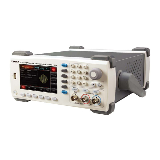
2.2 Introduction of Panels and Keys 2.2.1 Front Panel Function/arbitrary waveform generator provides users with a simple, intuitive, and easy to operate front panel. The front panel is shown in figure 2-1: 12.Menu 11. Number Buttons Button 13.Function Menu Softkeys 10. - Page 8 Modulation/Frequency Meter Input Terminal/Trigger Output Terminal During AM, FM, PM or PWM signal modulation, when modulation source is external, modulation signal is input through external modulation input. When frequency meter function is on, the signal to be measured is input through this interface;...
-
Page 9: Back Panel
2.2.2 Back Panel Figure 2-2 Structure of back panel 1. USB Interface PC software is connected through this USB interface. 2. Heat Dissipation Holes To ensure this instrument dissipate heat well, please do not block these holes. 3. Protection Fuse When AC input current is more than 2A, the fuse will cut off the AC input to protect the device. -
Page 10: Function Interface
2.2.3 Function interface Function interface is shown in figure 2-3: Channel Information Waveform Parameter List Softkey Labels Softkey Labels Figure 2-3 Function interface Detailed Description: Channel information: 1) “ON/OFF” on the left is channel open information. 2) There is a “Limit” logo indicates output range limit where white is valid and grey is invalid. -
Page 11: Chapter 3 Quick Start
3.1 Handle Adjustment The Tenma Series Function/Arbitrary Waveform Generator handle can be adjusted to carry and also support the unit. If the handle position needs to be changed, please hold the handle on both sides and pull out, then rotate the handle to the desired position, as shown in figure below: 3.2 Basic Waveform Output... -
Page 12: Amplitude Setting
3.2.2 Amplitude Setting Defaultwaveform: A sine wave of 100mV peak-peak value with 50Ω termination. Steps for changing the amplitude to 300mV are shown as follows: Press Menu→Waveform→Parameter→Amplitude in turn. Press Amplitude softkey again can switch between Vpp, Vrms, and dBm. Use number keys to input 300. -
Page 13: Square Wave Setting
3.2.4 Square Wave Setting Press Menu→Waveform→Type→Squarewave→Parameter in turn (press Type softkey to select only when Type label is not highlighted). If parameter needs to be set, press corresponding softkey to enter required numerical value and select the unit. Note: This parameter can be set by multifunctional control and direction buttons. 3.2.5 Pulse Wave Setting Default duty cycle of pulse wave is 50% and rising/falling edge time is 1us. -
Page 14: Dc Voltage Setting
3.2.6 DC Voltage Setting DC voltage output is the setting of DC offset on powering on. Steps for changing DC offset voltage to 3V are seen as follows: Press Menu→Waveform→Type→DC in turn to enter parameter setting mode. Use number keyboard to input the required number of 3. Select required unit V Note: This parameter can be set by multifunctional control and direction buttons. -
Page 15: Noise Wave Setting
3.2.8 Noise Wave Setting Default Quasi Gauss noise amplitude is 100mVpp and DC offset is 0mV. Steps for setting Quasi Gauss noise with 300mVpp amplitude and 1V DC offset are shown as follows: Press Menu→Waveform→Type→Noise→Parameter in turn to enter parameter editing mode. After setting, enter required number and unit. -
Page 16: Built-In Help System
3.4 Built-in Help System The built-in help system provides relevant information for any button or menu softkey. You also can use help topic list to get help. Operations for buttons help information are shown as following: Long press any softkey or button to display relevant information. If the content is more than 1 screen size, use softkey or multifunctional control to display the next screen. -
Page 17: Chapter 4 Advanced Applications
Chapter 4 Advanced Applications 4.1 Modulation Waveform Output 4.1.1 Amplitude Modulation (AM) Press Menu→Modulation→Type→ Amplitude Modulation in turn to start the AM function. Then the modulated waveform will output with modulation waveform and carrier wave set. Select carrier waveform AM carrier waveform can be: sine wave, square wave, ramp wave or arbitrary wave (except DC), and the default is sine wave. - Page 18 Carrier Wave Frequency Setting Settable carrier wave frequency range is different for different carrier waveforms. Default frequency of all carrier wave is 1kHz. The frequency setting range of each carrier wave can be seen in the following table: Frequency Carrier UTG1010A UTG1005A Wave...
- Page 19 Internal Source When modulation source is internal, modulation wave can be: sine wave, square wave, rising ramp wave, falling ramp wave, arbitrary wave and noise. After enabling AM function, the default of modulation wave is sine wave. If need to change it, press Carrier Wave →Parameter→Type in turn. ...
- Page 20 Modulation Depth Setting Modulation depth indicates the extent of amplitude variation and is expressed as percentage. Suitable setting range of AM modulation depth is 0% to 120%, and the default is 100%. When modulation depth is set to 0%, the constant amplitude (a half of the carrier wave amplitude that has been set) is output.
- Page 21 Set Modulation Signal Parameter After enabling the AM function, press Parameter softkey and the interface will appear as following: Press corresponding softkey, then enter required numerical value, and select the unit. Set Carrier Wave Signal Parameter Press Carrier Wave Parameter→Type→ Square Wave in turn to select square wave as carrier wave signal.
- Page 22 Press Parameter softkey again, and the interface will pop up as following: Press corresponding softkey, then enter required numerical value, and select the unit.
- Page 23 Set Modulation Depth After setting carrier wave parameter, press Return softkey to back to the following interface for setting modulation depth. Press Parameter →Modulation Degree softkey again, then enter number 80 and press % softkey with number keyboard for setting modulation depth. Enable Channel Output Press Channel button start channel output quickly.
- Page 24 The shape of AM modulation waveform checked through oscilloscope is shown as following:...
-
Page 25: Modulation Source Selection
4.1.2 Frequency Modulation (FM) In frequency modulation, modulated waveform is usually composed of carrier wave and modulation shape. Carrier wave frequency will change as the amplitude of modulation shape changes. Press Menu→Modulation→Type→ Frequency Modulation in turn to start the FM function. The device will output modulated waveform with modulation waveform and carrier wave set currently. - Page 26 Settable carrier wave frequency range is different of different carrier waveform. Default frequency of all carrier wave is 1kHz. The frequency setting range of each carrier wave can be seen in the following table: Frequency Carrier Wave 72-14111 72-14110 Waveform Minimum Maximum Minimum Maximum 1μHz...
- Page 27 Square wave: duty cycle is 50% Lead Ramp Wave: symmetry degree is 100% Tail Ramp Wave: symmetry degree is 0% Arbitrary Wave: Arbitrary wave length limit is 1kpts Noise: White Gauss noise External Source When modulation source is external, carrier waveform will be modulated by an external waveform. FM frequency deviation is controlled by ±5V signal level of external modulation input terminal on front panel.
- Page 28 Comprehensive Example: Make the instrument work in frequency modulation (FM) mode, then set a sine wave with 2kHz from the internal of the instrument as a modulation signal and a square wave with frequency of 10kHz and amplitude of 100mVpp as a carrier wave signal.
- Page 29 Press corresponding softkey, then enter required numerical value, and select the unit. Set Carrier Wave Signal Parameter Press Carrier Wave Parameter→Type→Sine Wave in turn to select sine wave as carrier wave signal.
- Page 30 Press Parameter softkey, and the interface will display as following: Press corresponding softkey first, then enter required numerical value, and select the unit.
- Page 31 Set Frequency Deviation After setting carrier wave parameter, press Return softkey to back to the following interface for setting frequency deviation. Press Parameter →Frequency Deviation softkey, then enter number 5 and press kHz softkey with number keyboard for setting frequency deviation.
- Page 32 Enable Channel Output Press Channel button to open channel output. The shape of FM modulation waveform checked through oscilloscope is shown as following:...
-
Page 33: Frequency Modulation (Fm)
4.1.3 Phase Modulation (PM) In phase modulation, modulated waveform is usually composed of carrier wave and modulation wave. The phase of carrier wave will change as the amplitude of modulation shape changes. Press Menu→Modulation→Type→ Phase Modulation in turn to start the PM function. The device will output modulated waveform with modulation waveform and carrier wave set currently. - Page 34 Settable carrier wave frequency range is different of different carrier waveform. Default frequency of all carrier wave is 1kHz. The frequency setting range of each carrier wave can be seen in the following table: Frequency Carrier Wave 72-14111 72-14110 Wavefrom Minimum Value Maximum Value Minimum Value Maximum Value 1μHz...
- Page 35 External Source When modulation source is external, carrier waveform will be modulated by an external waveform. PM phase deviation is controlled by ±5V signal level of external modulation input terminal on front panel. For example, if phase deviation value in parameter list has been set to 180º, +5V of external modulation signal is equivalent to 180º phase shift.
- Page 36 Set Modulation Signal Parameter Press Parameter softkey and the interface will show as following: Press corresponding softkey first, then enter required numerical value, and select the unit. Set Carrier Wave Signal Parameter Press Carrier Wave Parameter→Type→Sine Wave in turn to select sine wave as carrier wave signal.
- Page 37 Press Parameter softkey, and the interface will pop up as following: Press corresponding softkey, then enter required numerical value, and select the unit.
- Page 38 Set Phase Deviation Press Return softkey to back to the following interface for setting phase modulation. Press Parameter →Phase Deviation softkey, then enter number 200 and press º softkey with number keyboard for setting phase deviation.
- Page 39 Enable Channel Output Press Channel button to open channel output. The shape of PM modulation waveform checked through oscilloscope is shown as following:...
- Page 40 4.1.4 Amplitude Shift Keying (ASK) ASK represents digital signal “0” and “1” by changing amplitude of carrier wave signal. Carrier wave signal with different amplitude will be output on the basis of different logic of modulation signal. ASK Modulation Selection Press Menu→Modulation→Type→Amplitude Shift Keying in turn to start the ASK function, the device will output modulated waveform with ASK rate and carrier wave set currently.
- Page 41 Settable carrier wave frequency range is different of different carrier waveform. Default frequency of all carrier wave is 1kHz. The frequency setting range of each carrier wave can be seen in the following table: Frequency Carrier Wave 72-14111 72-14110 Waveform Minimum Value Maximum Value Minimum Value Maximum Value 1μHz...
- Page 42 External Source When modulation source is external, carrier waveform will be modulated by an external waveform. ASK output amplitude is determined by the logic level of modulation interface on front panel. For example, output the carrier wave amplitude of current setting when external input logic is low, and output carrier wave amplitude less than the amplitude of current setting when external input logic is high.
- Page 43 Press Parameter softkey, and the interface will pop up as following: Press corresponding softkey, then enter required numerical value, and select the unit.
- Page 44 Set ASK Rate After setting carrier wave parameter, press Return softkey to go back to the following interface for setting phase modulation. Press Parameter →Rate softkey again, then enter number 300 and press Hz softkey with number keyboard for setting ASK rate.
- Page 45 Enable Channel Output Press Channel button to open channel output quickly. The shape of ASK modulation waveform checked through oscilloscope is shown as following:...
-
Page 46: Amplitude Shift Keying (Ask)
4.1.5 Frequency Shift Keying (FSK) In frequency shift keying, rate of carrier wave frequency and hopping frequency can be changed. FSK Modulation Selection Press Menu→Modulation→Type→Frequency Shift Keying in turn to start the FSK function. The device will output modulated waveform with current setting. Carrier Wave Waveform Selection Press Carrier Wave Parameter softkey to enter carrier waveform selection interface. - Page 47 Settable carrier wave frequency range is different of different carrier waveform. Default frequency of all carrier wave is 1kHz. The frequency setting range of each carrier wave can be seen in the following table: Frequency Carrier Wave 72-14111 72-14110 Waveform Minimum Value Maximum Value Minimum Value Maximum Value 1μHz...
- Page 48 Internal Source When modulation source is internal, internal modulation wave is a square of 50% duty cycle (not adjustable). The FSK rate can be set to customize the moving frequency between carrier wave frequency and hop frequency. External Source When modulation source is external, carrier waveform will be modulated by an external waveform. FSK output frequency is determined by the logic level of modulation interface on front panel.
- Page 49 Comprehensive Example Firstly, make the instrument work in frequency shift keying (FSK) mode, then set a sine wave with 2kHz and 1Vpp from the internal of the instrument as a carrier wave signal, and set hop frequency to 800 Hz, finally, make carrier wave frequency and hop frequency move between each other with 200Hz frequency.
- Page 50 Press Parameter softkey again, and the interface will display the following: Press corresponding softkey first, then enter required numerical value, and select the unit. Set Hop Frequency and FSK Rate Press Return softkey to go back to the following interface.
- Page 51 Press Parameter softkey again, and the interface will pop up as following: Press corresponding softkey first, then enter required numerical value, and select the unit.
- Page 52 Enable Channel Output Press Channel button on front panel to open channel output. The shape of FSK modulation waveform checked through oscilloscope is shown as following:...
-
Page 53: Frequency Shift Keying (Fsk)
4.1.6 Phase Shift Keying (PSK) In phase shift keying, DDS function generator can be configured to move between two preset phase (carrier wave phase and modulation phase). Output carrier wave signal phase or hop signal phase on the basis of the logic of modulation signal. - Page 54 Press Parameter→Frequency softkey, then enter required numerical value, and select unit. Modulation Source Selection The Tenma Function/Arbitrary Waveform Generator can select internal modulation source or external modulation source. After enabling PSK function, the default of modulation source is internal. If need to change, press Parameter→Modulation→Source→External in turn.
- Page 55 External Source When modulation source is external, carrier waveform will be modulated by an external waveform. Carrier wave phase will be output when external input logic is low, and modulation phase will be output when external input logic is high. PSK Rate Setting When modulation source is internal, the moving frequency between carrier wave phase and modulation phase can be set.
- Page 56 Press Parameter softkey, and the interface will pop up as following: Press corresponding softkey, then enter required numerical value, and select the unit.
- Page 57 Set PSK Rate and Modulation Phase Press Return softkey to go back to the following interface: Press Parameter softkey, and the interface will display the following:...
- Page 58 Press corresponding softkey, then enter required numerical value, and select the unit. Enable Channel Output Press Channel button to open channel output quickly.
-
Page 59: Pulse Width Modulation (Pwm)
The shape of PSK modulation waveform checked through oscilloscope is shown as follows: 12. 4.1.7 Pulse Width Modulation (PWM) In pulse width modulation, modulated waveform is usually composed of carrier wave and modulation shape, and the pulse width of carrier wave will change as modulation shape amplitude changes. PWM Modulation Selection Press Menu→Modulation→Type→Pulse Width Modulation in turn to start the PWMK function. - Page 60 Carrier Wave Frequency Setting Settable range of pulse wave frequency is from 500uH to 25MHz, and the default frequency is 1kHz. Press Parameter→ Frequency softkey to change frequency, then enter required numerical value, and select unit. Carrier Wave Duty Cycle Setting Settable range of pulse wave duty cycle is 0.01%~99.99%, and the default duty cycle is 50%.
- Page 61 Internal Source When modulation source is internal, modulation wave can be: sine wave, square wave, rising ramp wave, falling ramp wave, arbitrary wave and noise, and the default wave is sine wave. If need to change, press Carrier Wave ParameterModulation Waveform in turn. ...
- Page 62 Comprehensive Example Make the instrument work in pulse modulation (PWM) mode, then set a sine wave with 1kHz from the internal of the instrument as a modulation signal and a pulse wave with 10kHz frequency, 2Vpp amplitude and 50% duty cycle as a carrier wave signal, finally, set duty cycle deviation to 40%.
- Page 63 Press corresponding softkey, then enter required numerical value, and select the unit. Set Carrier Wave Signal Parameter Press Carrier Wave Parameter softkey to enter carrier wave parameter setting interface.
- Page 64 Press Parameter softkey, and the interface will display as follows: If need to set parameter, press corresponding softkey first, then enter required numerical value, and select the unit.
- Page 65 Set Duty Cycle Deviation Press Return softkey to back to the following interface for duty cycle deviation setting: After pressing Parameter→Dutycycle softkey, enter number 40 and press % softkey with number keyboard for setting duty cycle deviation.
- Page 66 Enable Channel Output Press Channel button to open channel output quickly. The shape of PWM modulation waveform checked through oscilloscope is shown as follows:...
-
Page 67: Sweep Waveform Output
4.2 Sweep Waveform Output In sweep mode, frequency is output in linear or logarithmic way during the specified sweep time. Trigger source can be internal, external or manual trigger; and sine wave, square wave, ramp wave and arbitrary wave (except DC) can produce sweep output. -
Page 68: Start Frequency And Stop Frequency Setting
4.2.2 Start Frequency and Stop Frequency Setting Start frequency and stop frequency are the upper limit and lower limit of frequency scanning. Press Return softkey to back to sweep interface. Press Parameter→ Start Frequency→StopFrequency softkeys in turn, then enter number with number keyboard and press corresponding unit softkey. ... -
Page 69: Sweep Mode
4.2.3 Sweep Mode Linear sweep: waveform generator changes output frequency in the linear way during the sweep; Logarithmic sweep: waveform generator changes output frequency in logarithmic way; External sweep, the default is linear sweep way, if need to change, please press Type Logarithm softkey. 4.2.4 Sweep Time Set the required time from initial frequency to terminal frequency, the default is 1s, and the settable range is from 1ms to 500s. -
Page 70: Trigger Source Selection
4.2.5 Trigger Source Selection When signal generator receives a trigger signal, it generates a sweep output, and then waits for the next trigger signal. Sweep source can be internal, external or manual trigger. If need to change, press Parameter →Trigger Source softkey in turn. - Page 71 Comprehensive Example In sweep mode, set a sine wave signal with 1Vpp amplitude and 50% duty cycle as sweep signal, and sweep way is linear sweep, set the initial frequency of sweep to 1kHz and terminal frequency to 50kHz and sweep time to 2ms. Use rising edge trigger of internal source to to output sweep wave.
- Page 72 Press Parameter softkey, and the interface will display as follows: Press corresponding softkey, then enter required numerical value, and select the unit. Set Initial/Terminal Frequency, Sweep Time, Trigger Source and Trigger Edge Press Return softkey to the following interface:...
- Page 73 Press Parameter softkey, and the interface will display as follows: Press corresponding softkey, then enter required numerical value, and select the unit.
- Page 74 Enable Channel Output Press Channel button to open channel output quickly. The shape of sweep waveform checked through oscilloscope is shown as follows:...
-
Page 75: Arbitrary Wave Output
4.3 Arbitrary Wave Output Function/Arbitrary Waveform Generator stores totally 16 types of standard waveforms, names of each waveform can be found in table below (built-in arbitrary wave list). 4.3.1 Enable Arbitrary Wave Function Press Menu→Waveform→Type→Arbitrary Wave in turn to start the arbitrary wave function. The device will output arbitrary waveform with current setting. -
Page 76: Chapter 5 Fault Handling
Chapter 5 Fault Handling Possible troubles and trouble shooting methods are listed in following. Please follow the steps to handle problems. If you cannot handle them, please contact distributors of this product or local office, and also provide the equipment informations of your instrument (acquisition method: press Utility →System →System→About in turn). -
Page 77: Appendix A Factory Reset State
Appendix A Factory Reset State Parameters Factory Defaults Channel Parameters Current Carrier Wave Sine Wave 50Ω Output Outload Synchronous Output Channel Channel Output Close Channel Output Invert Close Amplitude Limit Close Amplitude Upper Limit Amplitude Lower Limit Basic Wave Frequency 1kHz Ampltide 100mVpp... - Page 78 FM Modulation Modulation Source Internal Modulation Shape Sine Wave Modulation Frequency 100Hz Fequency Offset 1kHz PM Modulation Modulation Source Internal Modulation Shape Sine Wave Modulation Phase Frequency 100Hz Phase Offset 180° PWM Modulation Modulation Source Internal Modulation Shape Pulse Wave Modulation Frequency 100Hz Duty Cycle Deviation...
- Page 79 Sweep Sweep Type Linear Initial Frequency 1kHz TerminalFrequency 2kHz Sweep Time Trigger Source Internal Parameters of System Sound of Buzzer Open , Number Format Backlight 100% Language* Determined by Factory Settings...
-
Page 80: Appendix B Technical Specifications
Appendix B Technical Specifications Type 72-14111 72-14110 Channel Single Channel Single Channel Max. Frequency 10MHz 5MHz Sample Rate 125MSa/s 125MSa/s Waveform Sine Wave, Square Wave, Triangle Wave, Pulse Wave, Ramp Wave, Noise, DC, Arbitrary Waveform Working Mode Output Stobe, Duration, Modulation, Scanning AM、FM、PM、ASK、FSK、PSK、PWM... - Page 81 1μHz~400kHz Frequency Range 1μHz Resolution 1%±2 mV(typical value,1kHz,1Vpp,symmetry 50%) Nonlinear Degree Symmetry 0.0% to 100.0% ≥400ns Min. Edge Time Pulse Wave 1μHz~5MHz 1μHz~5MHz Frequency Range 1μHz Resolution ≥80ns Pulse Eidth <24ns (typical value,1kHz,1Vpp) Lead/Tail Time <2% Overshoot(Typical Value) Jittering(Typical Value) 1ns+ 100ppm of period DC Offset Range(Peak Value AC+DC)...
- Page 82 <100kHz Amplitude Flatness(relative to sine 0.1dB wave of 1kHz, 1Vpp/50Ω) 100kHz~10MHz 0.2dB Waveform Output Typical value of 50Ω Impedance Insulation To earth wire, max.42Vpk Protection Short-circuit Protection Modulation Type AM Modulation Carrier Wave Sine Wave, Square Wave, Ramp Wave, Arbitrary Wave Source Internal/External Modulation Shape...
- Page 83 Source Internal/External Modulation Shape Square Wave of 50% duty cycle Modulation Frequency 2mHz~100kHz FSK Modulation Carrier Wave Sine Wave, Square Wave, Ramp Wave, Arbitrary Wave Source Internal/External Modulation Shape Square Wave of 50% duty cycle Modulation Frequency 2mHz~100kHz PSK Modulation Carrier Wave Sine Wave, Square Wave, Ramp Wave, Arbitrary Wave Source...
- Page 84 Front Panel Connector ±5Vpk during the whole measurement Modulation Input 20kΩ of input resistance Trigger Output TTL compatible Frequency Meter Input TTL compatible Frequency Meter Input Level TTL compatible 1Hz~100MHz Input Frequency Range Accuracy ±51ppm Frequency Resolution 6 bit/s Coupled Mode Direct Current General Technical Specifications Display...
-
Page 85: Appendix C Accessories List
Appendix C Accessories List Type UTG1000A Power line meets local country standard USB data cable (UT-D06) Standard Accessories BNC cable (1 meter) User CD... -
Page 86: Appendix D Maintenance And Cleaning
Appendix D Maintenance and Cleaning Cleaning • Clean the meter with a clean, soft cloth. • Do not use any chemicals, abrasives or solvents that could damage the meter. • Take great care when cleaning the screen to avoid scratches and use only a damp cloth to remove dirt. Warning: please confirm that the instrument is completely dry before powering on to prevent electrical short circuit and even personal injury due to moisture.
Need help?
Do you have a question about the 72-14110 and is the answer not in the manual?
Questions and answers