Advertisement
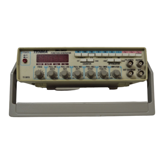
Tenma 72-5015 Function Generator
The Tenma 72-5015 Function generator is a multiple output repetitive function generator.
It is capable producing a sine, triangle or square wave with an adjustable frequency and
amplitude, as well as a digital square wave output. The waveform symmetry and base
amplitude voltage can be modified, as well as setting the frequency to sweep between
two limits at an adjustable rate.
Display and Display mode:
The frequency output display can be set to display the output frequency of the function
generator or can be used to measure an external digital frequency.
The display indicates the frequency and the lit indicator below the display indicates the
frequency range. The EXT button, when depressed, switches the display into counter
mode. Leaving this button out allows the display to indicate the frequency that the
generator is set at. There is also an attenuation button to the right of the EXT button.
This allows the incoming signal to be attenuated, or reduced by 20dB if the signal
amplitude coming in is too large.
Frequency setting:
The output frequency is controlled by a combination of controls. The range buttons
Quick Guide
select the range of the
signal to be generated.
Advertisement
Table of Contents

Related Manuals for Tenma 72-5015


Summary of Contents for Tenma 72-5015
- Page 1 Tenma 72-5015 Function Generator Quick Guide The Tenma 72-5015 Function generator is a multiple output repetitive function generator. It is capable producing a sine, triangle or square wave with an adjustable frequency and amplitude, as well as a digital square wave output. The waveform symmetry and base amplitude voltage can be modified, as well as setting the frequency to sweep between two limits at an adjustable rate.
- Page 2 These buttons are used in conjunction with the vernier knob to select the desired frequency. This is a continuously adjustable knob that allows the adjustment of the frequency between 0.2 and 2 of the selected frequency range. Waveform Shape: The waveform shape is selected by three buttons located at the upper right hand corner.
- Page 3 connect to the unit to obtain your useable signal. The TTL/CMOS outpu jack generates a digital square wave that is representative of the frequency set, with the period matting that of the analog waveform. The voltage on this is adjusted by the Digital adjustment knob. Pushing the knob in locks the output in 5V mode.
Need help?
Do you have a question about the 72-5015 and is the answer not in the manual?
Questions and answers