Table of Contents
Advertisement
Advertisement
Table of Contents

Related Manuals for TSPROF K01RP


Summary of Contents for TSPROF K01RP
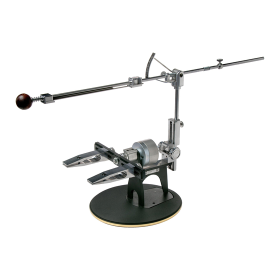
- Page 1 Instruction’s manual sharpening system TSPROF K01RP, K03 Made in Russia...
-
Page 3: Table Of Contents
CONTENTS Specifications.....................3 Parts........................4 Safety, rules of operation...................6 Preparing......................7 Assemby......................8 Assembly of the abrasive holder..............8 Adjustment of the rotary gear fixation effort..........8 Installation of the clamp..................9 Full flat grind clamping..................9 Clamping of a knife with a tapered blade.............10 Installation of an abrasive................10 Parking, setting sharpening angle..............11 Calibration......................14 Calibration of horizontal frame..............14... -
Page 4: Specifications
Maximum 23 ° Device overall dimensions No more than: (without clips, Stand and abrasive holder) mm. 250x220x330 Weight of the K01RP body without main units. 1.68 kg. Weight of the K03 body without main units. 2,05 kg. 710mm The length of the abrasive holder assembled. -
Page 7: Safety, Rules Of Operation
Security Attention! Before using the device, please read this manual attentively. Incorrect handling of this prod- uct could possibly result personal injury or physical damage. The manufacturer assumes no responsibility for any damage caused by mishandling that is beyond normal usage defined in this manuall. -
Page 8: Preparing
Preparation Construction of the device may be changed by the manufacturer in order to improve operation. Option 1. Apply saddles to the contact surfaces of the G-Clamp(14E) from the spare parts package. Stick to the back side of the body 5 bumpers (14F) from the spare parts package. -
Page 9: Assemby
Assembly Assemble the abrasive holder, and remove the stopper together with the amortization spring. Install the abrasive holder in sleeve hub (1), apply a drop of liquid lubricant. then set spring and amortization limiter (2). 3. Set the rotary mechanism retention force. For K03 by turning of the calibration wheel, set a necessary rotary gear fixation effort Choose an effort so it doesn’t flip during the process of sharpening. -
Page 10: Installation Of The Clamp
Install the clamp on the frame and tighten the thumbscrews. * You can use TSPROF clamps of any configuration. Locate the clamps at the needed distance from each other depending on the length and the blade geometry. 5. Install the knife, loosening the far (2) and near (1), clamping screws. -
Page 11: Clamping Of A Knife With A Tapered Blade
If the knife blade has a tappered blade, tighten first near clamping screws with a little effort (1), then a far (2) weakening the closest screws while tighten far screw. The jaws thus should be at an angle to each other. If the length of the far clamping screw is not enough, replace it with a longer M4x16 (14G) from the spare parts package. -
Page 12: Parking, Setting Sharpening Angle
Pulling the near thrust bar towards the handle, squeeze the spring and insert the abrasive. Parking For convenience, set the abrasive holder to the parking. As it shown on the picture, place parking boot on the parking disc. Adjustment of the sharpening angle Install a digital protractor on the site for protractor and reset it. - Page 13 Install an abrasive and lean it against the cutting edge. Put digital protractor on abrasive holder (abrasive holder must be located at the center). By the rotation of the angle adjust- ment thumbsrew, set the desired angle of sharpening. Far limiter Near limiter You can fix the angle of the sharpening with the help of a locking screw if necessary, as shown in the picture below.
- Page 14 Loosen the near stopper, place the near edge of abrasive on the most far tip of the blade, leaving about 1.5 - 2 cm. Move near limiter to the hub and tighten the thumbscrew. Actions for the far limiter are similar.
-
Page 15: Calibration
Calibration Calibration of the Profile device is made during production. Setting or calibration can be dis- trupted during transportation, or if disassembling of the units requiring calibration took place. Deviation <= 0.3 ° are not essential. It is not recommended to produce adjustments for the elimination of non-essential deviations. - Page 16 Holding the frame by hand, loosen the lock nut with 10 mm spanner. By the turning of the frame, achieve zero value of the digital protractor. While holding the frame by hand, tighten the lock nut. Option 2. Place a ruler vertically touched to the edge of the frame and rest it in a flat table surface. Make measurements on both sides.
-
Page 17: Turning Clamp Angle Calibration
Adjusting the angles symmetry while turning the clamp Calibration is required to equalize the asymmetry of the angles while turning the clamp which may appear during transportation, as well as during long term use. Digital protractor is required for the calibration. The device should be firmly fixed on a flat surface. Set the calibration plate (14D) from the spare parts packet in the clamp. -
Page 18: Digital Prottuctor Platform Horizontal Calibration
Adjustment of the horizontal protractor platform Mount the digital protractor on the frame and reset its value. Place the digital protractor on the ground for the protractor. If the deviation is more than 0,3 °, slightly loosen the adjusting screw with an 2mm hex key. While holding with the hand from the bottom, adjust inclination by the digital protractor, then tighten the upper adjust- ment screw. -
Page 19: Adjustment Of The Rack And Pinion Lift Movement
Adjustment of the Rack and Pinion lift movement With the 2 mm hex wrench (14A) from the spare parts package, adjust the pinch screws 1 and 2, as it shown in the picture below, to avoid the up and down free movement of the rack and pinion lift. -
Page 20: Digital Prottuctor Platform Parallel Calibration
Adjusting the parallelism of the protractor’s platform and turning axis * Performs after adjustment of the angles symmetry while turning. Place the digital protractor on the plate and reset its value. Next, set the protractor on a platform (as shown in the figure), and if the value exceeds 0,3 ° perform the adjustment. With the 2mm hex key. -
Page 21: Warranty
Warranty This product is warranted for 3 years, starting from the date of the products purchase. During the warranty period, the manufacturer is obliged to repair, or replace the whole product or its parts if appear any defects caused by poor quality of materials or assembly. This warranty is recognized only if the product was used in accordance with the operating instructions, it was not repaired or disassembled by unauthorized experts, and has not been damaged due to improper handling, and also the complete set of products retained. - Page 22 Deviation during the frame rotation Checked « » ‘ Inspector SIGNATURE...
- Page 24 Address: 426065, Russia, Izhevsk, Str. 10 let Oktybrya 60, office 405. Phone: +1 877 63-88-248 (US toll free) E-mail: sales@tsprof.com Manufacturer Website: tsprof.com...
Need help?
Do you have a question about the K01RP and is the answer not in the manual?
Questions and answers