Advertisement
Quick Links
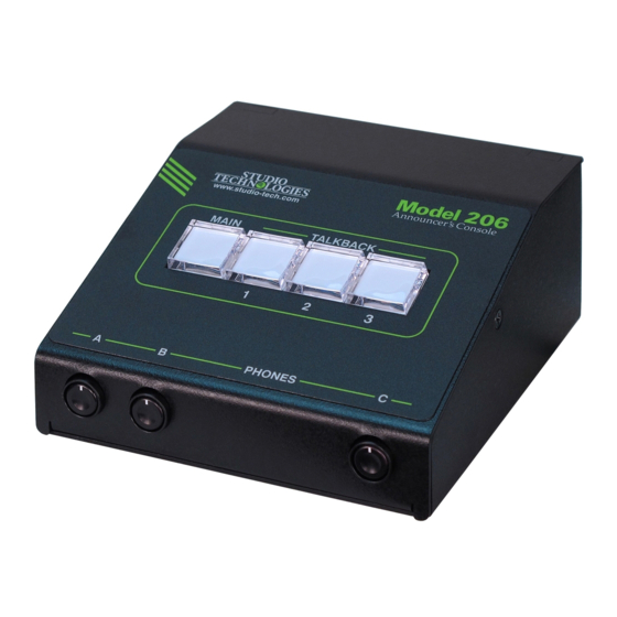
Model 206 Announcer's Console
User Guide
Issue 2, October 2018
This User Guide is applicable for serial numbers
M206-00151 to 00500 with application firmware 1.2 and later
and STcontroller application version 1.07.00 and later.
Copyright © 2018 by Studio Technologies, Inc., all rights reserved
www.studio-tech.com
50646-1018, Issue 2
Advertisement

Related Manuals for Studio Technologies 206


Summary of Contents for Studio Technologies 206
- Page 1 Issue 2, October 2018 This User Guide is applicable for serial numbers M206-00151 to 00500 with application firmware 1.2 and later and STcontroller application version 1.07.00 and later. Copyright © 2018 by Studio Technologies, Inc., all rights reserved www.studio-tech.com 50646-1018, Issue 2...
- Page 2 This page intentionally left blank.
-
Page 3: Table Of Contents
Revision History ............4 Introduction ..............5 Getting Started ............. 10 Operation ..............19 Technical Notes ............24 Specifications ............... 28 Appendix A: Model 206 Block Diagram ......29 Model 206 User Guide Issue 2, October 2018 Studio Technologies, Inc. Page 3... -
Page 4: Revision History
Revision History Issue 2, October 2018: • Documents addition of the Push to Mute/Tap to Latch main button operating mode. Issue 1, April 2018: • Initial release. Issue 2, October 2018 Model 206 User Guide Page 4 Studio Technologies, Inc. -
Page 5: Introduction
Applications and streaming broadcast applications. The unit is housed in a compact, rugged The Model 206 on its own can provide an steel enclosure that’s intended for table- “all-Dante” solution for one on-air talent top use. Calling the Model 206 “cute” or location. - Page 6 And with the Set up, configuration, and operation of three talkback audio channels available as the Model 206 is simple. An etherCON® Dante output channels, routing to inputs RJ45 jack is used to interconnect with a...
- Page 7 Ethernet Data and PoE AES67 interoperability standard. In this mode the four transmitter (output) chan- The Model 206 connects to a local area net- nels will function in multicast; unicast is not work (LAN) by way of a standard 100 Mb/s supported.
- Page 8 The Model 206 provides two remote con- Configuration Flexibility trol inputs. Configuration choices allow The Model 206 can be configured to meet these to be assigned to work in parallel the needs of specific applications and user with the main, talkback 1, talkback 2, or preferences.
- Page 9 Model control the level of a stereo input signal 206 by way of Dante inputs 1 and 2 and as it is routed to the left and right chan- is routed in stereo to the left and right nels of the headphone output.
-
Page 10: Getting Started
ANNOUNCER’S CONSOLE Three system modes select the overall An Ethernet data connection with Power- way in which the Model 206 functions. The over-Ethernet (PoE) capability will be on-air mode is optimized for applications made using either a standard RJ45 patch... - Page 11 This could be connected to the current draw. To prevent this undesirable Model 206 by way of the microphone output condition ensure that no input audio signal connector. This would not create a problem...
- Page 12 3-conductor jack is located on the Model microphone output circuitry. 206’s back panel and provides access to The microphone output can be connected the two remote control inputs. The input to balanced (differential) analog micro- circuitry is “active low,”...
- Page 13 The Model 206 uses the Ultimo 4-input/ KHz will be appropriate. While technically 4-output integrated circuit to implement the Model 206 can serve as a clock master the Dante functionality. The Model 206 can for a Dante network (as can all Dante-...
- Page 14 LED, orange in color patible with personal computers running and visible on the back of the Model 206’s Windows operating systems that are enclosure adjacent to the microphone version 7 and later. STcontroller versions input connector, can act as a guide when 1.07.00 and later will fully support the Mod-...
- Page 15 In these applica- pot B adjusts its level. A stereo pair can tions it’s typical to want the user to have enter the Model 206 by way of Dante input a single potentiometer to simultaneously channels 3 and 4. These signals, whose...
- Page 16 A setting in STcontroller is used to config- plication. If a “full mix” is being provided to ure the headphone output’s minimum level. the Model 206’s Dante inputs then locally In the –40 dB setting the minimum head- provided sidetone won’t be needed and the phone output level is approximately 40 dB off configuration should be selected.
- Page 17 Whenever the main button is pressed tion until the main button is released. the audio signal will become active on Upon Model 206 power up the main the Dante output channel and the micro- button will be in its inactive state and its phone output connector.
- Page 18 Upon Model be used separately and not impact each 206 power up the talkback buttons will other. This also allows both the main and be in their inactive state and their LEDs talkback pushbuttons to be used simulta- will not be lit.
-
Page 19: Operation
This mode is The Model 206 should have been placed not appropriate when headphones are in the desired physical location. Using the going to be connected to the Model 206! Studio Technologies STcontroller software application the unit’s configuration should Remote Control Inputs have been selected to meet the needs of There are two remote control inputs. - Page 20 (timing reference) is being received. It will slowly flash green when Functions within the Dante Controller and this specific Model 206 is part of a Dante STcontroller software applications allow network and is serving as the clock mas- a specific Model 206 unit to be identified.
- Page 21 • Latching: If this mode is selected the microphone output connector that’s located audio signal associated with the Dante on the back panel of the Model 206. How main output channel and the microphone the button functions will depend on the con-...
- Page 22 Dante talkback output channel will change state. • Push to Mute/Tap to Latch: This mode is Upon Model 206 power up the audio sig- a combination of the Push to Mute and nals on the Dante talkback output chan- Latching modes.
- Page 23 The three rotary potentiometers (pots), a talkback function is active. The on-air located on the Model 206’s front panel, al- mode will be appropriate for all on-air low level adjustment of the Dante audio in- broadcast applications where it’s impera-...
-
Page 24: Technical Notes
“in” position Using the Dante Controller software ap- when protection from an unwanted change plication the Model 206’s IP address and is beneficial. related network parameters can be set for a fixed (static) configuration. While this is a... - Page 25 Refer to the Audinate website firmware version to be identified. Connect (www.audinate.com) for details on optimiz- the Model 206 unit to the network and let ing networks for Dante applications. it connect and start to function. Then, after starting STcontroller, review the list of iden-...
- Page 26 ANNOUNCER’S CONSOLE here to the naming convention required by 4. Apply power to the Model 206 by con- the Model 206, the name of the zip file itself necting to a Power-over-Ethernet (PoE) will include the file’s version number. For Ethernet source.
- Page 27 Model 206’s defaults applied to the Model 206. Upon power up to be reset to the factory values. From the main button’s LED will flash on and off...
-
Page 28: Specifications
Gain: 35, 43, 52, 59 dB, selectable Ethernet: Neutrik etherCON RJ45 Frequency Response: 25 Hz to 20 kHz, –3 dB USB: type A receptacle (located inside Model 206’s Distortion (THD+N): <0.018%, measured at 35 dB enclosure and used only for updating firmware) -
Page 29: Appendix A: Model 206 Block Diagram
MODEL 206 ANNOUNCER’S CONSOLE Appendix A: Model 206 Block Diagram The following block diagram shows a simplified version of the Model 206’s microphone input and microphone output circuitry. Model 206 User Guide Issue 2, October 2018 Studio Technologies, Inc. Page 29...
Need help?
Do you have a question about the 206 and is the answer not in the manual?
Questions and answers