
Related Manuals for DeDietrich B control panel


Summary of Contents for DeDietrich B control panel
- Page 1 B Control panel English Package MA1 [Basic] 03/14/08 Please Read & Safe This Manual for Future Reference Instructions for use, Electrical connection, Start up 94862242...
-
Page 2: Table Of Contents
CONTENTS 1. INTRODUCTION ..............3 2. -
Page 3: Introduction
1. INTRODUCTION The B control panel is used on the following The boiler must be connected by a qualified De Dietrich boilers: professional. Strict compliance with these usage, electrical connection and start up - GT 120 A and GT 1200 A. -
Page 4: Assembly, Electrical Connections And Fitter Settings
5. ASSEMBLY, ELECTRICAL CONNECTIONS AND FITTER SETTINGS Assembling the control panel Installing the boiler sensor • • Refer to the assembly sheet provided with the Refer to the assembly sheet provided with the instructions for the boiler. instructions for the boiler. Electrical connections Electrical connections shall be made respecting the Electrical connections shall be carried out... - Page 5 Basic connections SENSOR Minimum wire gauge 0.75mm2 = 18 AWG S ECS S CH 1.5mm2 = 14 AWG 19 18 17 16 15 14 120V - 60Hz 3 x 1,5 mm mini. 3 x 0,75 mm mini. 3 x 0,75 mm GT 120 A mini.
- Page 6 Control Connections & Options SENSOR Sensor cables must be separated from cables 120V circuits (see page 4). Minimum wire gauge 0.75mm2 = 18 AWG 1.5mm2 = 14 AWG S ECS S CH 19 18 17 16 15 14 120V - 60Hz Removable Removable bridge...
- Page 7 "FITTER" SETTINGS The settings defined below are applicable for various functions, and the installation configu- ration. They can only be modified by qualified professional. Access to d.h.w. pump timeout adjustment potentiometers and the d.h.w. load temperature limiter. 8575N056A 8575N054A - Remove the top panel from the boiler. - Remove the P.C.B.
- Page 8 Deactivating the domestic hot water priority When the domestic hot water priority is deac- tivated, heating is no longer cut off during domes- tic hot water heating phases. - Switch off the boiler power supply. - Remove the front panel, proceeding as follows: Lift the window.
- Page 9 SKELETON DIAGRAMS 8578N006B (8578-4902B)
-
Page 10: Usage
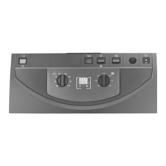
6. USAGE 8578N003 1. Main On/Off switch For preparation of domestic hot water. Position 9. Light On Display domestic hot water temperature Position 10. Electronic thermostat 2. Alarm light Setting the average domestic hot water storage tem- This light comes On when the burner is in safety (out of perature order) Note:... -
Page 11: Messages - Alarms
7. MESSAGES - ALARMS The display may show the following messages in the case of a malfunction: MESSAGE FAILURE PROBABLE CAUSE REMEDY The corresponding sensor A A L L S S 0 0 Boiler sensor Inform the fitter. circuit is interrupted or See comments below. - Page 12 8578-4016A B control panel Spare parts for GT 120 A - GT 1200 A Note : when ordering spare parts, do not forget to provide the code number given in the list opposite the part reference. & & " "...
- Page 13 B control panel Mark Code No. DESCRIPTION Mark Code No. DESCRIPTION 8578-7000 Complete standard control panel 8575-8019 Card supports GT 120, GT 1200V 8578-8501 Standard card cover 8578-4905 Diem Easy standard GT120 harness 9786-4061 Front panel with skin 8578-4906 Burner cable GT120...
- Page 16 Bp 30 – 57, RUE DE LA Gare F – 67580 MERTZWILLER Tel: +33/3/88/80/27/00 – Fax: +33/3 88 80 27 99 Ni IRC : 347 555 559 RCS STRASBOURG www.dedietrich-thermique.com DDR AMERICAS INC In Canada: In USA or South America: 1090 Fountain St., Unit #10...
Need help?
Do you have a question about the B control panel and is the answer not in the manual?
Questions and answers