Advertisement
Quick Links
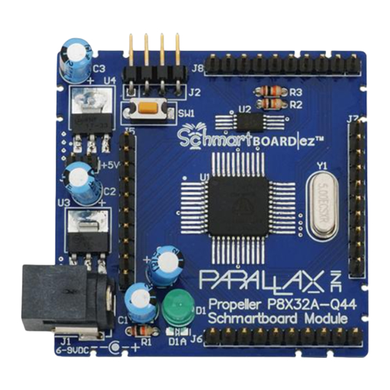
P8X32A-Q44 SchmartBoard (#27150)
Want to learn how to surface solder but don't know where to start? Parallax Inc has partnered with
SchmartBoard to bring an easy electronic circuit prototyping system in the form of a kit. This kit is a
perfect starting point; the SchmartBoard technology makes surface mount soldering easy. Once
completed, the board will host Parallax's most powerful microcontroller on this convenient development
platform, allowing access to all 32 I/O pins of the multi-core Propeller chip.
This board is designed to accommodate either surface mount or through-hole components in some
circuits. Wherever there is an option, both types of components have been included. The surface mount
soldering options, while more challenging, provides easier access to the J5 header.
Features
Propeller microcontroller
Headers for easy access to the I/O pins
for prototyping
AC barrel jack for power supply
convenience
Schmartboard technology for easy
surface mount soldering
3.3 & 5.0 VDC on-board regulators
Surface mount and through-hole
component configuration options
Key Specifications
Power requirements: 6 to 9 VDC
Communication: Serial for programming
via Prop Plug (not included)
Operating temperature: -32 to +158 °F (-0 to +70 °C)
Dimensions: 2 x 2 x 0.56 in (50.60 x 50.60 x 14.45 mm)
Precautions
Please read entire document before beginning assembly.
Take all the necessary precautions for handling a hot soldering iron, solder, and soldering
equipment, including a well ventilated work area and proper safety gear including eye protection.
Do not power unit until all parts are attached.
Check soldering joints throughout the project, this will help ensure no cold solder joints have
been overlooked; and help when it comes to troubleshooting.
Copyright © Parallax Inc.
Web Site: www.parallax.com
Forums: forums.parallax.com
Sales: sales@parallax.com
Technical: support@parallax.com
P8X32A-Q44 SchmartBoard (#27150)
Office: (916) 624-8333
Fax: (916) 624-8003
Sales: (888) 512-1024
Tech Support: (888) 997-8267
v1.2 9/10/2009 Page 1 of 9
Advertisement

Related Manuals for Parallax 27150


Summary of Contents for Parallax 27150
- Page 1 P8X32A-Q44 SchmartBoard (#27150) Want to learn how to surface solder but don’t know where to start? Parallax Inc has partnered with SchmartBoard to bring an easy electronic circuit prototyping system in the form of a kit. This kit is a perfect starting point;...
-
Page 2: Bill Of Materials
Warning Any attempt to assemble or complete this kit voids any warranty that is covered by Parallax Inc. and/or SchmartBoard. Inspect your board carefully for manufacturing flaws before proceeding. If you have questions regarding assembly please review the steps and if further questions arise you can call our Technical Support staff at 888-997-8267 and they will be happy to help with your questions. - Page 3 Step 1: Unpack contents of package and compare with the Bill of Materials above to ensure all parts are accounted for. If any parts are missing, contact Parallax directly (contact information is at the top of the first page). Step 2: Wash the PCB with alcohol to clean the surface of any grease or oils, and allow it to dry before soldering.
- Page 4 The SchmartBoard uses lead-free solder and is suggested as the type to use. Copyright © Parallax Inc. P8X32A-Q44 SchmartBoard (#27150) v1.2 9/10/2009 Page 4 of 9...
- Page 5 C3 - 10 µF capacitor C2 - 10 µF capacitor R1 - 470 Ω resistor D1 - Red LED J3 - 2-pin jumper J1 - power jack Copyright © Parallax Inc. P8X32A-Q44 SchmartBoard (#27150) v1.2 9/10/2009 Page 5 of 9...
- Page 6 PCB for soldering. Step 12: Carefully clean off any extra flux that may be on the board and allow to fully dry before connecting to power or programming tool. Copyright © Parallax Inc. P8X32A-Q44 SchmartBoard (#27150) v1.2 9/10/2009 Page 6 of 9...
- Page 7 LED on I/O pin P23 to confirm operation. Change the Pin constant and circuit to test the rest of the I/O pins. '' Title: SchmartBoard Kit Test '' Author: Parallax Inc. _clkmode = xtal1 + pll16x 'System clock _xinfreq = 5_000_000 'set 80 MHz...
-
Page 8: Additional Resources
Pluggable Wires Male-Female 12.5" - (1 pack of 10) #800-00029 Pluggable Wires Female-Female 12.5" - (1 pack of 5) #27926 Parallax Object Exchange: http://obex.parallax.com Parallax Forums: http://forums.parallax.com Copyright © Parallax Inc. P8X32A-Q44 SchmartBoard (#27150) v1.2 9/10/2009 Page 8 of 9... -
Page 9: Troubleshooting
4. Verify voltage of the power going to the EEPROM; Vdd (pin 8) should be ~3.3 VDC. For further assistance, contact Parallax Tech Support (support@parallax.com, or call 1-888-997-8267 toll- free in the Continental US, Monday through Friday from 7 a.m. to 5 p.m. Pacific Time. - Page 10 PIN_12 PIN_44 PIN_13 PIN_43 PIN_14 PIN_42 PIN_15 PIN_41 PIN_16 3.3V 3.3V PIN_38 PIN_19 PIN_37 PIN_20 PIN_36 PIN_21 PIN_35 PIN_22 PIN_34...
Need help?
Do you have a question about the 27150 and is the answer not in the manual?
Questions and answers