Advertisement
Quick Links
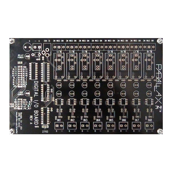
Digital I/O Board Kit (#27113)
The Parallax Digital I/O Board Kit enables your microcontroller to interface to high voltage circuits
allowing you to read up to 8 optically isolated inputs and control up to 8 isolated outputs. Inputs can be
a voltage from 5-30VDC (AC compatible) and outputs can be either mechanical or solid state relays that
can switch up to 12A loads, such as cooling fans, solenoids, heating elements and more.
Simple parallel input/output control for ease of use or you can use the serial interface to minimize I/O pin
usage. The logic circuits operate from 3.3V to 5V making them compatible with most microcontrollers.
The ICs in the kit are all socketed making replacement easy should it ever be necessary. 8 green and 8
red LEDs indicate the status of input and outputs. 2 yellow LEDs indicate relay/logic power. Inputs can
be configured to handle a different range of input voltages by changing a couple of components.
Features
Mechanical or Solid State Relay output
Configurable Input Voltage range
Serial or parallel interface to inputs/outputs
LED indication of power and input/output status
AppMod compatible connection for Board of Education
Key Specifications
Power requirements: 12VDC @ 1A for relay power and 3.3 – 5VDC for logic power
Communication: Parallel or Synchronous Serial
Operating temperature: +32 to +158°F (0 to +70°C)
Dimensions: 7.25" L x 4.50" W x 1.00" H (184.1mm x 114.3mm x 25.4mm)
Application Ideas
Isolated power control of high voltage/current devices from your microcontroller, such as heating
elements, blower fans, solenoids, lighting systems and more
Isolated monitoring of high voltage signals such as doorbell, alarm or other signals.
Product Notices
Relays are not included with this kit and must be purchased separately. Mechanical Relays are
part #400-00052 and Solid State Relays are part #400-00053.
This product comes as a kit and must be assembled by the customer. Soldering experience is
required to assemble this kit and the following tools are required; Safety Glasses, Soldering Iron,
Solder, Flux (optional), Diagonal Cutters (to remove extra leads), Needle-Nosed Pliers (optional,
to bend/form leads)
This product is capable of switching high voltages. Observe the safety precautions listed in this
documentation.
Copyright © Parallax Inc.
Web Site: www.parallax.com
Forums: forums.parallax.com
Sales: sales@parallax.com
Technical: support@parallax.com
Digital I/O Board Kit (#27113)
Office: (916) 624-8333
Fax: (916) 624-8003
Sales: (888) 512-1024
Tech Support: (888) 997-8267
v1.0 2/19/2010 Page 1 of 13
Advertisement

Related Manuals for Parallax 27113


Summary of Contents for Parallax 27113
- Page 1 Digital I/O Board Kit (#27113) The Parallax Digital I/O Board Kit enables your microcontroller to interface to high voltage circuits allowing you to read up to 8 optically isolated inputs and control up to 8 isolated outputs. Inputs can be a voltage from 5-30VDC (AC compatible) and outputs can be either mechanical or solid state relays that can switch up to 12A loads, such as cooling fans, solenoids, heating elements and more.
- Page 2 Check back periodically for updates or additional examples including example programs, customer applications, articles, etc. http://www.parallax.com Search for 27113 on our website. Copyright © Parallax Inc. Digital I/O Board Kit (#27113) v1.0 2/19/2010 Page 2 of 13...
- Page 3 Install the sockets, S1- S8 and S9, S10 and S11 as shown to the right. Notches should be toward the top. Solder these in place. Copyright © Parallax Inc. Digital I/O Board Kit (#27113) v1.0 2/19/2010 Page 3 of 13...
- Page 4 ‘setting the input voltage range’. Install the 1.5K resistors R25-R32 into the positions shown at right. Color code is: Brown, Green, Red, Gold Inset shows details. Copyright © Parallax Inc. Digital I/O Board Kit (#27113) v1.0 2/19/2010 Page 4 of 13...
- Page 5 Step 9: Install the 1K resistors R1-R8, R33 and R42 into the positions shown at right. Color code is: Brown, Black, Red, Gold Inset shows details. Copyright © Parallax Inc. Digital I/O Board Kit (#27113) v1.0 2/19/2010 Page 5 of 13...
- Page 6 Note: 12 Terminal Blocks must be snapped together for the relay connections. These slide together vertically to create one long strip. Copyright © Parallax Inc. Digital I/O Board Kit (#27113) v1.0 2/19/2010 Page 6 of 13...
- Page 7 Inset is from other side. Step 15: Install Capacitors C1-C4 into their respective positions as shown at right. Observe proper polarity on C4. C1-C3 are non-polarized. Inset shows details. Copyright © Parallax Inc. Digital I/O Board Kit (#27113) v1.0 2/19/2010 Page 7 of 13...
- Page 8 You do not need to fill all slots to use this board. Copyright © Parallax Inc. Digital I/O Board Kit (#27113) v1.0 2/19/2010 Page 8 of 13...
- Page 9 2-position terminal block next to it. The terminal block is labeled + and – which the DC barrel jack is center tip positive, making it compatible with our power supplies (Parallax recommends #750-00007). Minimal reverse polarity protection is provided by diode D25.
-
Page 10: Communication Protocol
LOW. Note: The Parallel interface is unaffected by this jumper. Therefore the parallel signals from the 74HC165 are always inverted Copyright © Parallax Inc. Digital I/O Board Kit (#27113) v1.0 2/19/2010 Page 10 of 13... - Page 11 When connecting the V+ pin to VIN on another board, be sure that board does not have its own power supply. The target board will now get power from the Digital I/O Board. Copyright © Parallax Inc. Digital I/O Board Kit (#27113) v1.0 2/19/2010 Page 11 of 13...
-
Page 12: Specifications
Input 3 Signal IN_4 Input 4 Signal IN_5 Input 5 Signal IN_6 Input 6 Signal IN_7 Input 7 Signal IN_8 Input 8 Signal Ground Ground Copyright © Parallax Inc. Digital I/O Board Kit (#27113) v1.0 2/19/2010 Page 12 of 13... -
Page 13: Module Dimensions
Relay Output Enable (input from host microcontroller) Module Dimensions Module Schematic A full size schematic in PDF format is available from the product page on our website. Copyright © Parallax Inc. Digital I/O Board Kit (#27113) v1.0 2/19/2010 Page 13 of 13... - Page 14 Mouser Electronics Authorized Distributor Click to View Pricing, Inventory, Delivery & Lifecycle Information: Parallax 27113...
Need help?
Do you have a question about the 27113 and is the answer not in the manual?
Questions and answers