
Related Manuals for Samsung MT6402-48A


Summary of Contents for Samsung MT6402-48A
- Page 1 MT6402-48A Installation Manual Describes product installation and requirement procedure. Document Version 1.0 May 2019 Document Number: 2600-00O5UIGAA...
- Page 2 SAMSUNG Electronics Co., Ltd., its subsidiaries or employees for any direct or indirect loss or damage caused by omissions from or inaccuracies in this document. SAMSUNG Electronics Co., Ltd. reserves the right to change details in this publication without notice. SNMTC-v3-0312 This manual should be read and used as a guideline for properly installing and/or operating the product.
-
Page 3: Table Of Contents
Fixing Wall Type ......................... 30 MMU Tilting & Swivelling ...................... 39 Removing the MMU ........................ 69 Chapter 3 Connecting Cables 75 Cabling Procedure .......................... 75 Guidelines for Cable Connections .................... 76 Cable Path Inspection ........................ 76 Cable Cutting .......................... 77 Cable Installation ........................ 77 Connector Attachment ...................... 78 Cable Binding .......................... 78 Identification Tag Attachment .................... 79 Cabling Diagram .......................... 80 Grounding ............................ 81 Connecting Ground Cable ...................... 81 Power Cabling .......................... 84 Connecting Power Cable ...................... 85 Interface Cable Connection ...................... 89 Connecting LINK Cable ....................... 89 MT6402-48A Installation Manual v1.0 Copyright © 2019, All Rights Reserved. - Page 4 Confidential Contents Connecting UDA Cable ....................... 92 Remove UDA Cable ........................ 95 Chapter 4 Inspect the Installation 97 Appendix A Acronyms 101 Appendix B Clean the Optical Connectors 102 Introduction .......................... 102 Cleaning the MPO Connector .................... 102 Measure the Optical Output and Connecting the Optical Connector ........ 104 Appendix C Standard Torque 106 MT6402-48A Installation Manual v1.0 Copyright © 2019, All Rights Reserved.
- Page 5 Figure 39. MMU Down Tilting (6) ........................ 44 Figure 40. Bracket Change for MMU Up Tilting (1) .................. 46 Figure 41. Bracket Change for MMU Up Tilting (2) .................. 47 Figure 42. Bracket Change for MMU Up Tilting (3) .................. 48 Figure 43. Bracket Change for MMU Up Tilting (4) .................. 50 Figure 44. Bracket Change for MMU Up Tilting (5) .................. 51 Figure 45. Lifting MMU ........................... 52 Figure 46. Fixing Pole Mount Bracket Assembly‐Top (Up‐Tilting) (1) ............. 53 Figure 47. Fixing Pole Mount Bracket Assembly‐Top (Up‐Tilting) (2) ............. 53 MT6402-48A Installation Manual v1.0 Copyright © 2019, All Rights Reserved.
- Page 6 Connecting LINK Cable (3) ...................... 91 Figure 85. Connecting UDA Cable (1) ...................... 93 Figure 86. Connecting UDA Cable (2) ...................... 93 Figure 87. Connecting UDA Cable (3) ...................... 94 Figure 88. Connecting UDA Cable (4) ...................... 94 Figure 89. UDA Cable Removal; Push Pull Type .................... 96 Figure 90. Installation Inspection Procedure .................... 97 Figure 91. Cleaning MPO Connector_Plug side (1) .................. 103 Figure 92. Cleaning MPO Connector_Plug side (2) .................. 103 Figure 93. Cleaning MPO Connector_Receptacle side (1)................ 104 Figure 94. Cleaning MPO Connector_Receptacle side (2)................ 104 MT6402-48A Installation Manual v1.0 Copyright © 2019, All Rights Reserved.
- Page 7 Table 24. Parts and Tools for Connecting Ground Cable ................ 81 Table 25. Parts and Tools for Connecting Power Cable ................. 85 Table 26. DC Power Cable/Connector Pin Map ..................... 85 Table 27. Parts and Tools for LINK Cable Connection .................. 89 Table 28. Parts and Tools for Connecting UDA Cable .................. 92 Table 29. UDA Cable Pin Map ........................ 92 Table 30. UDA Cable Removal Tools; Push Pull Type .................. 95 Table 31. Construction Situation Checklist .................... 98 Table 32. MPO Connector Cleaning Tools .................... 103 Table 33. Standard Torque Value for Fastening Bolts ................. 106 Table 34. Brass Bolts Torque Value ...................... 106 Table 35. Connector Connection Torque Value ................... 106 MT6402-48A Installation Manual v1.0 Copyright © 2019, All Rights Reserved.
-
Page 8: Preface
Confidential Preface This manual describes how to install the CBRS MMU (MT6402-48A) including how to connect the cables. Conventions in this Document Samsung Networks product documentation uses the following conventions. Symbols Symbol Description Indicates a task. Indicates a shortcut or an alternative method. -
Page 9: Revision History
Clean the Optical This appendix describes the procedure of cleaning the optical Connectors connector and cleaning tool. Appendix C Standard Torque This appendix describes the standard torque when fastening the bolt. MT6402-48A Installation Manual v1.0 Copyright © 2019, All Rights Reserved. -
Page 10: Personal And Product Safety
The cable between the power distribution point and the installed equipment must have a minimum cross-sectional area of 10 mm Maintenance Maintenance must only be carried out by a suitably trained and competent MT6402-48A Installation Manual v1.0 Copyright © 2019, All Rights Reserved. - Page 11 If equipment is grounded through a cabinet or rack, make sure it is done so properly according to the installation instructions. Power Supply Connection The equipment is designed to be powered from a -48 V DC supply. Power MT6402-48A Installation Manual v1.0 Copyright © 2019, All Rights Reserved.
- Page 12 Devices that are not marked according to the relevant national safety standards may produce hazardous conditions on the network. Product Disposal To reduce the environmental impact of products, Samsung has joined WEEE compliance activities. The WEEE symbol on the product indicates that the product is covered by the European Directive 2002/96/CE for the disposal of Waste Electrical and Electronic Equipment (WEEE).
-
Page 13: Equipment Markings
The system must be installed in a restricted area, and make sure the work is done by personnel properly trained for the job. Protective earth MMU should be grounded. MT6402-48A Installation Manual v1.0 xiii Copyright © 2019, All Rights Reserved. -
Page 14: Chapter 1 Before Installation
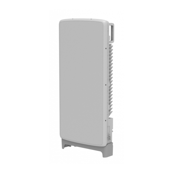
MMU View and External Interface This section provides the physical structure overview of the MMU and its interfaces. MMU View The following figure depicts the physical structure of the MMU. MT6402-48A Installation Manual v1.0 Copyright © 2019, All Rights Reserved. - Page 15 Confidential Chapter 1 Before Installation MT6402-48A Installation Manual v1.0 Copyright © 2019, All Rights Reserved.
- Page 16 Confidential Chapter 1 Before Installation MT6402-48A Installation Manual v1.0 Copyright © 2019, All Rights Reserved.
-
Page 17: Specifications
Telcordia GR-63-CORE Section 4.4.5 IP rating IP65 FCC Title 47 CFR Part 15 subpart B FCC Title 47 CFR Part 96 Beam Steering Range Horizontal -45°3 to +45°3 @ 3 dB Loss MT6402-48A Installation Manual v1.0 Copyright © 2019, All Rights Reserved. - Page 18 Confidential Chapter 1 Before Installation Item MT6402-48A Vertical -17°2 to +17°2 @ 3 dB Loss Safety UL 60950-1 UL 60950-22 Installation Pole mount, Wall mount MT6402-48A Installation Manual v1.0 Copyright © 2019, All Rights Reserved.
-
Page 19: Cautions For Installation
When operator installs the MMU, the MMU must be within the protective angle (left/right side 45° each from the central axis) to prevent the MMU from lightning damage. MT6402-48A Installation Manual v1.0 Copyright © 2019, All Rights Reserved. - Page 20 Confidential Chapter 1 Before Installation MT6402-48A Installation Manual v1.0 Copyright © 2019, All Rights Reserved.
-
Page 21: Installation Tools
Tightening M12 hexagonal bolt Tape Measure 16 ft./150 ft. Measuring length Level Normal Levelling horizontality and verticality Power Extension Cable 100 ft. Basic tool Hammer Drill Normal Wall Type Drilling MT6402-48A Installation Manual v1.0 Copyright © 2019, All Rights Reserved. - Page 22 Removing cable sheath in. (4 to 16 mm) Nipper Basic Tool Cutting cable Flush cutter Basic Tool For cutting cable tie Industrial Scissor Basic Tool Cutting Knife Basic Tool Cutting MT6402-48A Installation Manual v1.0 Copyright © 2019, All Rights Reserved.
- Page 23 The required installation tools may vary depending on the site conditions. In addition to the basic tools, protractor, ladder, safety equipment and cleaning tools must be arranged considering the site conditions. MT6402-48A Installation Manual v1.0 Copyright © 2019, All Rights Reserved.
-
Page 24: Chapter 2 Installing System
The figure below depicts the overall procedures for installing the MMU. Figure 3. Procedure to Install the MMU Foundation Work Bringing in Items Unpacking and Transporting Unpacking Items Fixing Unit Bracket Fixing System Fixing Mounting Bracket Fixing MMU MT6402-48A Installation Manual v1.0 Copyright © 2019, All Rights Reserved. - Page 25 Confidential Chapter 2 Installing System MT6402-48A Installation Manual v1.0 Copyright © 2019, All Rights Reserved.
- Page 26 Confidential Chapter 2 Installing System MT6402-48A Installation Manual v1.0 Copyright © 2019, All Rights Reserved.
- Page 27 Confidential Chapter 2 Installing System MT6402-48A Installation Manual v1.0 Copyright © 2019, All Rights Reserved.
-
Page 28: Transporting And Unpacking
Unpack only external packing, leave the internal packing in unpacked status. Unpack the inner packaging after each system is placed on its installation location. Dispose by-products (packaging waste) in accordance with management rules. Do not recycle the by-products. MT6402-48A Installation Manual v1.0 Copyright © 2019, All Rights Reserved. -
Page 29: Mmu Handling
MMU or its packaging box. Lifting Hazard Single person lift could cause injury. Get the help when moving or lifting the MMU. Figure 7. Transporting the MMU MT6402-48A Installation Manual v1.0 Copyright © 2019, All Rights Reserved. - Page 30 Confidential Chapter 2 Installing System MT6402-48A Installation Manual v1.0 Copyright © 2019, All Rights Reserved.
- Page 31 Confidential Chapter 2 Installing System MT6402-48A Installation Manual v1.0 Copyright © 2019, All Rights Reserved.
- Page 32 Confidential Chapter 2 Installing System MT6402-48A Installation Manual v1.0 Copyright © 2019, All Rights Reserved.
- Page 33 Confidential Chapter 2 Installing System MT6402-48A Installation Manual v1.0 Copyright © 2019, All Rights Reserved.
- Page 34 Confidential Chapter 2 Installing System MT6402-48A Installation Manual v1.0 Copyright © 2019, All Rights Reserved.
- Page 35 Confidential Chapter 2 Installing System MT6402-48A Installation Manual v1.0 Copyright © 2019, All Rights Reserved.
- Page 36 Confidential Chapter 2 Installing System MT6402-48A Installation Manual v1.0 Copyright © 2019, All Rights Reserved.
- Page 37 Confidential Chapter 2 Installing System MT6402-48A Installation Manual v1.0 Copyright © 2019, All Rights Reserved.
- Page 38 Confidential Chapter 2 Installing System MT6402-48A Installation Manual v1.0 Copyright © 2019, All Rights Reserved.
- Page 39 Confidential Chapter 2 Installing System MT6402-48A Installation Manual v1.0 Copyright © 2019, All Rights Reserved.
- Page 40 Confidential Chapter 2 Installing System MT6402-48A Installation Manual v1.0 Copyright © 2019, All Rights Reserved.
- Page 41 Confidential Chapter 2 Installing System MT6402-48A Installation Manual v1.0 Copyright © 2019, All Rights Reserved.
- Page 42 Confidential Chapter 2 Installing System MT6402-48A Installation Manual v1.0 Copyright © 2019, All Rights Reserved.
- Page 43 Confidential Chapter 2 Installing System MT6402-48A Installation Manual v1.0 Copyright © 2019, All Rights Reserved.
- Page 44 When the position is determined for placing the system, place the system on that position and then mark the positions where anchor bolts will be fixed. This will reduce the marking error. MT6402-48A Installation Manual v1.0 Copyright © 2019, All Rights Reserved.
- Page 45 Confidential Chapter 2 Installing System MT6402-48A Installation Manual v1.0 Copyright © 2019, All Rights Reserved.
- Page 46 Confidential Chapter 2 Installing System MT6402-48A Installation Manual v1.0 Copyright © 2019, All Rights Reserved.
- Page 47 Confidential Chapter 2 Installing System MT6402-48A Installation Manual v1.0 Copyright © 2019, All Rights Reserved.
- Page 48 Confidential Chapter 2 Installing System MT6402-48A Installation Manual v1.0 Copyright © 2019, All Rights Reserved.
- Page 49 Confidential Chapter 2 Installing System MT6402-48A Installation Manual v1.0 Copyright © 2019, All Rights Reserved.
- Page 50 Confidential Chapter 2 Installing System MT6402-48A Installation Manual v1.0 Copyright © 2019, All Rights Reserved.
- Page 51 Confidential Chapter 2 Installing System MT6402-48A Installation Manual v1.0 Copyright © 2019, All Rights Reserved.
- Page 52 Confidential Chapter 2 Installing System MT6402-48A Installation Manual v1.0 Copyright © 2019, All Rights Reserved.
- Page 53 Confidential Chapter 2 Installing System MT6402-48A Installation Manual v1.0 Copyright © 2019, All Rights Reserved.
- Page 54 Confidential Chapter 2 Installing System MT6402-48A Installation Manual v1.0 Copyright © 2019, All Rights Reserved.
- Page 55 Confidential Chapter 2 Installing System MT6402-48A Installation Manual v1.0 Copyright © 2019, All Rights Reserved.
- Page 56 Confidential Chapter 2 Installing System MT6402-48A Installation Manual v1.0 Copyright © 2019, All Rights Reserved.
- Page 57 Confidential Chapter 2 Installing System MT6402-48A Installation Manual v1.0 Copyright © 2019, All Rights Reserved.
- Page 58 Confidential Chapter 2 Installing System MT6402-48A Installation Manual v1.0 Copyright © 2019, All Rights Reserved.
- Page 59 Confidential Chapter 2 Installing System MT6402-48A Installation Manual v1.0 Copyright © 2019, All Rights Reserved.
- Page 60 Confidential Chapter 2 Installing System MT6402-48A Installation Manual v1.0 Copyright © 2019, All Rights Reserved.
- Page 61 Confidential Chapter 2 Installing System MT6402-48A Installation Manual v1.0 Copyright © 2019, All Rights Reserved.
- Page 62 Confidential Chapter 2 Installing System MT6402-48A Installation Manual v1.0 Copyright © 2019, All Rights Reserved.
- Page 63 Confidential Chapter 2 Installing System MT6402-48A Installation Manual v1.0 Copyright © 2019, All Rights Reserved.
- Page 64 Confidential Chapter 2 Installing System MT6402-48A Installation Manual v1.0 Copyright © 2019, All Rights Reserved.
Need help?
Do you have a question about the MT6402-48A and is the answer not in the manual?
Questions and answers