Table of Contents

Related Manuals for CHERUBINI TDS COMPACT


Summary of Contents for CHERUBINI TDS COMPACT
- Page 1 A510038 TDS COMPACT CENTRALINA PER TENDE DA SOLE ELECTRONIC AWNING CONTROL UNIT FUNKEMPFÄNGER ZU MARKISEN RÉCEPTEUR POUR STORES CENTRALITA PARA TOLDOS ISTRUZIONI - INSTRUCTIONS - EINSTELLANLEITUNGEN INSTRUCTIONS - INSTRUCCIONES...
-
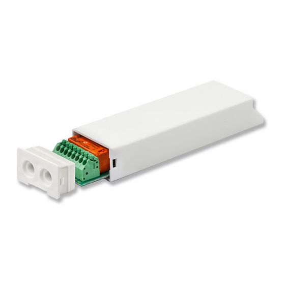
Page 2: Technical Features
CARATTERISTICHE TECNICHE TECHNICAL FEATURES - Alimentazione 230 V / 50Hz - Power supply 230 V / 50 Hz - Potenza assorbita 0,5 W - Power consumption 0,5 W - Frequenza radio 433,92 MHz - Radio Frequency 433,92 MHz - Codifica Rolling code - Decoder System Rolling code... -
Page 3: Table Of Contents
Table of contents: Technical features ....................p. 2 Safety instructions / Electrical connections ............. p. 23 Compatible remote controls ................... p. 24 Key to symbols ....................... p. 24 Command sequences example ................p. 25 Function open/close programming remote control Skipper PLUS - Skipper LUX - Skipper P-LUX ............ -
Page 4: Safety Instructions / Electrical Connections
SAFETY INSTRUCTIONS - Only professional technicians must perform installation, complying with all safety instructions, especially those regarding electrical connections. - To avoid short circuits, arrange an automatic bipolar switch with opening distance of the contacts of at least 3 mm before the circuit. - If not used, the white wire must be insulated. -
Page 5: Compatible Remote Controls
COMPATIBLE REMOTE CONTROLS LED - Skipper Skipper Skipper A530058 Remote Skipper Skipper Control with 4 Display - Skipper independent Skipper Skipper channels Skipper Skipper Channel selector Activating/ Deactivating the Sun sensor Check the specific Skipper instruction book Skipper GIRO Wall GIRO stop DOWN... -
Page 6: Command Sequences Example
COMMAND SEQUENCES EXAMPLE Most of the command sequences have three distinct steps, at the end of which the motor indicates if the step has been concluded positively or not, by turning in different ways. This section is provided to demonstrate the motor indications. The buttons must be pressed as shown in the sequence, without taking more than 4 seconds between one step and the next. -
Page 7: Function Open/Close Programming Remote Control Skipper Plus - Skipper Lux - Skipper P-Lux
FUNCTION OPEN/CLOSE PROGRAMMING REMOTE CONTROL SKIPPER PLUS - SKIPPER LUX - SKIPPER P-LUX To prevent accidental changes to the programming of the motor during the daily use of the remote control, the possibility of programming is disabled automatically 8 hours after sending the last sequence (A+B or B+C). -
Page 8: Function Open/Close Programming Remote Control Skipper - Giro Series
FUNCTION OPEN/CLOSE PROGRAMMING REMOTE CONTROL SKIPPER - GIRO SERIES To prevent accidental changes to the programming of the motor during the daily use of the remote control, the possibility of programming is disabled automatically 8 hours after sending the last sequence (A+B or B+C). CHECKING THE STATUS OF THE FUNCTION Open programming... -
Page 9: Operational Modes
OPERATIONAL MODES The A510038 control units may be connected to motors with either mechanical or electronic limit switches. NOTES ON ADJUSTMENT OF THE LIMIT SWITCHES To adjust the limit switches refer to the motor manual. - MECHANICAL LIMIT SWITCH Connect the control unit. Move the motor in the desired direction. Turn the motor’s adjustment screws to bring the awning to the desired position. -
Page 10: Automatic Disabling Of The First Remote Control Setting Function
After the last confirmation movement, the motor starts a series of UP and DOWN movements: the first lasts 2 seconds, the next ones go to the limit switch positions (motors with mechanical limit switches) or long movements - max 10 seconds (motors with electronic limit switches). -
Page 11: Closing Force Adjustment (Only Motors With Mechanical Limit Switches)
CLOSING FORCE ADJUSTMENT (Only motors with mechanical limit switches) This system ensures, when used it with box awnings, that the awning remains completely closed, without the awning fabric undergoing excessive stress from pulling. The control unit has been set in the factory to a predetermined closing force setting, equal to 40% of the rated torque. -
Page 12: First Middle Positions
FIRST MIDDLE POSITIONS This optional function enables the awning to be moved to a first preferred middle position. The first middle position is memorized as descent time starting from the upper limit switch. SETTING FIRST MIDDLE POSITION Procedure Command sequence 1) Press the A+B buttons for at least 2 s. -
Page 13: Second Middle Positions
SECOND MIDDLE POSITIONS This optional function is useful to open the awning automatically using the WindTec Lux sensor when ambient light exceeds the set threshold. This position is intended only for use in combination with the “Light” automatic movement given by the WindTec Lux light sensor. There are no manual controls to bring the awning into this position. -
Page 14: 2-Button Switch
2-BUTTON SWITCH It is possible to run the motor through a switch connected to the control unit with three wires (up, down and common). The switch must be equipped with mechanical or electrical interlock, to prevent two commands being sent simultaneously. Furthermore, the switch must be an unstable pushbutton: releasing it, the switch opens. -
Page 15: Operation In Up-Down Mode (For 2 Independent Buttons)
OPERATION IN UP-DOWN MODE (for 2 independent buttons) Pressing one of the two buttons and releasing, the motor drives to the desired direction until it reaches the limits. To stop the motor STOP before reaching the limits press again the same button. -
Page 16: Compatible Devices
COMPATIBLE DEVICES RUGIADA (TX RAIN-SENSOR) Sensor element Set button RUGIADA - Ref. A520016 Power Supply 230 Vac ANEMOMETERS Set button Wind-speed WINDTEC LUX - Ref. A520008 WINDTEC - Ref. A520007 tuning Sun-sensor tuning SETTING To associate the sensor to the control unit, a remote control must be already memorised. The setting sequence is the following: 2 sec DELETING... -
Page 17: Enable / Disable The Sun Sensor (Windtec Lux)
ENABLE / DISABLE THE SUN SENSOR (WindTec Lux) To enable (automatically) or disable (manually) the sun sensor refer to the instruction manual provided with the sensor or the remote control you want to use. MISTRAL SENSOR It detects movements caused by the wind on the awning arms. SET BUTTON SELECTOR MISTRAL- Ref. -
Page 18: Deleting The Limit Switch Positions
DELETING THE LIMIT SWITCH POSITIONS During operation, the control unit automatically acquires the mechanical limit switch positions set on the motor. In the event that the length or position of the mechanical limit switches need to be changed, the positions already acquired by the control unit will need to be deleted. -
Page 19: Setting The A530058 Remote Control With 4 Independent Channels
SETTING THE A530058 REMOTE CONTROL WITH 4 INDEPENDENT CHANNELS The A530058 remote control must be set from another Skipper or Giro Series remote control that has already been programmed. • Press the A and B buttons at the same time. •... -
Page 20: Full Memory Clearing
FULL MEMORY CLEARING The full memory clearing can be performed in two ways: 1) WITH THE REMOTE CONTROL Tn: Already programmed remote control Tn (4 sec) 2) WITH THE WHITE WIRE Do this operation only in case of emergency, if all remote controls are no longer operating. To delete the memory we have to access the white wire of the control unit. -
Page 21: The Rotation Direction Of The Motor
SPECIAL FUNCTIONS SHORT-TERM SETTING OF A REMOTE CONTROL AND SETTING THE ROTATION DIRECTION OF THE MOTOR This function makes it possible to store a remote control temporarily, for example, with the purpose of setting the limit switches during assembly in the factory. A later final saving of the remote control will be possible using the appropriate command sequence (see: “SETTING THE FIRST REMOTE CONTROL”). -
Page 22: Guarantee / Eu Declaration Of Conformity
EU DECLARATION OF CONFORMITY CHERUBINI S.p.A. declares that the product is in conformity with the relevant Union harmonisation legislation: Directive 2014/53/EU, Directive 2011/65/EU. The full text of the EU declaration of conformity is available upon request at the following website: www.cherubini.it. - Page 24 CHERUBINI S.p.A. Via Adige 55 25081 Bedizzole (BS) - Italy Tel. +39 030 6872.039 | Fax +39 030 6872.040 info@cherubini.it | www.cherubini.it CHERUBINI Iberia S.L. Avda. Unión Europea 11-H Apdo. 283 - P. I. El Castillo 03630 Sax Alicante - Spain Tel.
Need help?
Do you have a question about the TDS COMPACT and is the answer not in the manual?
Questions and answers