Advertisement
Quick Links
Assembly Tips
Review entire instruction manual before proceeding.
•
Production Basics nameplate indicates front of frame.
•
Legs are adjustable in 2-inch increments between 30-36 or 36-42
•
inches high to customize worksurface height.
Don't be a slave to gravity-recruit a co-worker to help you install and
•
correctly position components and accessories.
References to 'Left' and 'Right' are oriented as if you were facing the
•
front of the workstation.
Need help? Call Assembly Support at 800.318.2770.
•
RTW Support Rail
(channel faces inward)
Production Basics, Inc.
Massachusetts, USA
1303A301
A S S E M B L Y M A N U A L
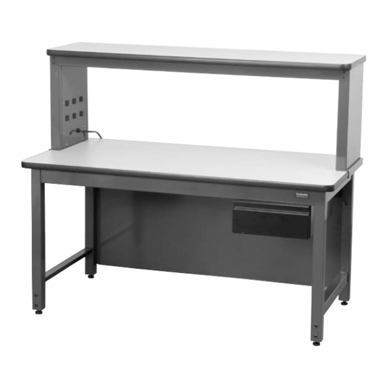
RTW Table with optional accessories
Right Frame Leg
(channel faces inward)
Mounting holes for Uprights
must be at back of Frame Leg.
800.318.2770
617.926.8100
W o r k s t a t io n s
RTW Table
Item Numbers 3000-3115
P A R T S A N D H A R D W A R E
Frame Legs (left and right specific)
Leg Adjusters
RTW Support Rail
Chrome Mounting Plate
Worksurface
Leveling Feet
Wood Screws
Basic Bolts
Allen Wrench
Other Items Needed (not included)
Phillips head drill or screwdriver
Rubber mallet
Level
Tape Measure
Basic Bolt
Wood Screw
1.
Open the cartons and identify the left and right Frame
Legs and RTW Support Rail. Position Frame Legs so
that mounting holes for Uprights are at the back of the
RTW Table. Frame Legs have a horizontal open channel
that faces inward.
2.
Screw the levelling feet all the way into the leg adjusters.
3.
Slide leg adjusters into bottom of Frame Legs. Determine
desired table height and secure position by inserting two
(2) Basic Bolts. Adjust leveling feet if necessary.
Fax: 617.926.8010
www.pbasics.com
Q U A N T I T Y
2
4
2
4
1
4
12
16
1
Chrome Mounting
Plate
1
Advertisement

Related Manuals for Production Basics RTW Table 3000

Summary of Contents for Production Basics RTW Table 3000
- Page 1 Assembly Tips Level Review entire instruction manual before proceeding. Tape Measure • Production Basics nameplate indicates front of frame. • Legs are adjustable in 2-inch increments between 30-36 or 36-42 • inches high to customize worksurface height. Don’t be a slave to gravity-recruit a co-worker to help you install and •...
- Page 2 Locate Support Rail. Loosely attach the Chrome Mounting Plate to the outside of the Support Rail with two (2) Basic Bolts using Allen wrench provided. RTW Support Rail Slip the Chrome Mounting Plate into the slot on the frame leg as shown. The leg will be between the Chrome Mounting Plate and the Support Rail.
Need help?
Do you have a question about the RTW Table 3000 and is the answer not in the manual?
Questions and answers