Table of Contents
Advertisement
Quick Links
Advertisement
Table of Contents

Summary of Contents for Radio Bridge RBS306-VM30-US
- Page 1 Wireless Voltage Sensor User Guide ERSION 2019 EPTEMBER...
-
Page 2: Table Of Contents
IRELESS OLTAGE ENSOR ABLE OF ONTENTS QUICK START ........................2 OVERVIEW .......................... 2 2.1. Sensor Overview ........................2 2.2. Revision History .........................3 2.3. Document Conventions ......................3 2.4. Part Numbers ..........................3 TECHNICAL SPECIFICATIONS ....................3 3.1. Absolute Maximum Ratings ......................3 BATTERY LIFE........................4 TEST MESSAGES ........................ -
Page 3: Quick Start
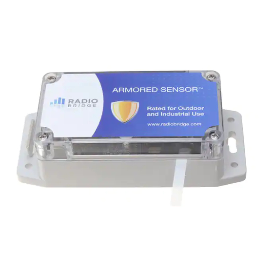
VERVIEW 2.1. Sensor Overview The wireless sensors designed and manufactured by Radio Bridge provide full sensor to cloud solutions for Internet of Things (IoT) applications. The voltage sensor uses a 10-bit ADC to measure an analog value between 0-30V and provides 10mV of resolution. If the measured value rises above or falls below the configured thresholds, an alert is sent over the wireless network. -
Page 4: Revision History
Font / Icon Meaning Important notes Warnings and cautions 2.4. Part Numbers Table 3 Part Numbers Part Number Rating Wireless Region RBS306-VM30-US Outdoor/Industrial LoRaWAN North America RBS306-VM30-EU Outdoor/Industrial LoRaWAN Europe 3. T ECHNICAL PECIFICATIONS 3.1. Absolute Maximum Ratings Table 4 Absolute Maximum Ratings... -
Page 5: Battery Life
Radio Bridge sensors are shipped with lithium batteries, and these are recommended when the battery needs to be eventually replaced. -
Page 6: Test Messages
If the standard Radio Bridge console (console.radiobridge.com) is not used, refer to this section to decode the sensor data and configure the sensor through downlink messages. 6.1. Common Messages There are common messages across all wireless sensors that are defined in the document “Common Sensor Messages”... -
Page 7: Uplink Messages
IRELESS OLTAGE ENSOR 6.2. Uplink Messages The uplink message (sensor to web application) specific to the sensor is defined in following table. The common uplink messages are not included in this section (see common messages document). Table 5 Uplink Message 0x14: Voltage Measurement Event Byte Description Voltage Measurement Event Payload (see Voltage... -
Page 8: Downlink Messages
IRELESS OLTAGE ENSOR 6.3. Downlink Messages The downlink message (web application to sensor) specific to the sensor configuration is defined in following table. The common downlink messages are not included in this section (see common messages document). Table 7 Downlink Configuration Message 0x14 Byte Description Mode: 0x00 for Threshold, or 0x01 for Report on Change Defined by Mode (See Mode sections) -
Page 9: Report On Change Mode
IRELESS OLTAGE ENSOR The Restoral Margin is used for the upper and lower thresholds and requires the measurement value to cross back over the threshold a certain amount before a new event is reported. This prevents excessive event messages if the measurement is at or near the threshold. -
Page 10: Periodic Reports
IRELESS OLTAGE ENSOR 6.3.3. Periodic Reports The voltage measurement sensor can also send periodic updates, and this is defined in byte 1 of both modes. A setting of 0 will disable periodic reporting. The period is defined in 1 hour increments when the most significant bit is 0, and it is defined in 1 minute increments when the most significant bit is 1 as shown in the following table. -
Page 11: Mechanical Drawings
IRELESS OLTAGE ENSOR 7. M ECHANICAL RAWINGS The mechanical drawings provided in this section are for the main body of the sensor. All dimensions are inches unless otherwise noted. 7.1. I 01 S NDOOR ENSORS © 2019, R OPYRIGHT ADIO RIDGE IRELESS OLTAGE... -
Page 12: Armored Outdoor/Industrial Rbsx06 Sensors
IRELESS OLTAGE ENSOR 7.2. A 06 S RMORED UTDOOR NDUSTRIAL ENSORS © 2019, R OPYRIGHT ADIO RIDGE IRELESS OLTAGE ENSOR... -
Page 13: Regulatory And Compliance
(2) this device must accept any interference received, including interference that may cause undesired operation. Per FCC 15.21, Changes or modifications not expressly approved by Radio Bridge could void authority to operate the devices. Sigfox RBS101, RBS104, and RBS105 sensors FCC ID: 2APNUSFM10R2... -
Page 14: Customer Support
UPPORT Radio Bridge offers free technical support at: https://support.radiobridge.com Radio Bridge also offers technical support plans and service packages to help our customers get the most out of their Radio Bridge products. ISCLAIMERS Information in this document is subject to change without notice and does not represent a commitment on the part of Radio Bridge.


Need help?
Do you have a question about the RBS306-VM30-US and is the answer not in the manual?
Questions and answers