Table of Contents
Advertisement
Available languages
Available languages
Quick Links
Betriebsanleitung
Operating
instructions
Version: 03.2020.0
ID: 900.000.0134
Copyright 2020 AFRISO-EURO-INDEX GmbH. Alle Rechte vorbehalten.
0123
GWG 23
Typ: GWG 23-Ro
Typ: GWG 23-Wa
Typ: GWG 23-T
Lindenstraße 20
74363 Güglingen
Telefon +49 7135 102-0
Service +49 7135 102-211
Telefax +49 7135 102-147
info@afriso.com
www.afriso.com
Advertisement
Table of Contents

Related Manuals for AFRISO GWG 23 Series


Summary of Contents for AFRISO GWG 23 Series
- Page 1 Betriebsanleitung Operating instructions GWG 23 Typ: GWG 23-Ro Typ: GWG 23-Wa Typ: GWG 23-T Copyright 2020 AFRISO-EURO-INDEX GmbH. Alle Rechte vorbehalten. Lindenstraße 20 74363 Güglingen Telefon +49 7135 102-0 0123 Service +49 7135 102-211 Telefax +49 7135 102-147 info@afriso.com Version: 03.2020.0...
- Page 2 Betriebsanleitung Grenzwertgeber für Außenbehälter GWG 23 Typ: GWG 23-Ro Typ: GWG 23-Wa Typ: GWG 23-T Copyright 2020 AFRISO-EURO-INDEX GmbH. Alle Rechte vorbehalten. Lindenstraße 20 74363 Güglingen Telefon +49 7135 102-0 0123 Service +49 7135 102-211 Telefax +49 7135 102-147 info@afriso.com Version: 03.2020.0...
-
Page 3: Über Diese Betriebsanleitung
Über diese Betriebsanleitung Über diese Betriebsanleitung Diese Betriebsanleitung beschreibt den Grenzwertgeber für Außenbehälter „GWG 23-Ro / GWG 23-Wa / GWG 23-T“ (im Folgenden auch „Produkt“). Diese Betriebsanleitung ist Teil des Produkts. • Sie dürfen das Produkt erst benutzen, wenn Sie die Betriebsanleitung vollständig gelesen und verstanden haben. -
Page 4: Informationen Zur Sicherheit
Informationen zur Sicherheit Informationen zur Sicherheit Warnhinweise und Gefahrenklassen In dieser Betriebsanleitung finden Sie Warnhinweise, die auf potenzielle Gefahren und Risiken aufmerksam machen. Zusätzlich zu den Anweisungen in dieser Betriebsanleitung müssen Sie alle am Einsatzort des Produktes gel- tenden Bestimmungen, Normen und Sicherheitsvorschriften beachten. Stel- len Sie vor Verwendung des Produktes sicher, dass Ihnen alle Bestimmun- gen, Normen und Sicherheitsvorschriften bekannt sind und dass sie befolgt werden. - Page 5 Informationen zur Sicherheit Lediglich die Grenzwertgeber „GWG 23-Ro / GWG 23-Wa“ mit der gelben Armatur für Rohrmontage oder Wandmontage haben eine Zulassung für Ex-Zone 0 und dürfen an eigensicheren Stromkreisen in Ex-Zone 0 errichtet werden. Eine andere Verwendung ist nicht bestimmungsgemäß und verursacht Gefahren.
- Page 6 Informationen zur Sicherheit Qualifikation des Personals Montage, Inbetriebnahme, Wartung und Außerbetriebnahme dieses Pro- dukts dürfen nur von einem qualifizierten Fachbetrieb vorgenommen werden, der über eine entsprechende Zertifizierung verfügt und folgende Anforderun- gen erfüllt: • Einhaltung aller am Einsatzort des Produkts geltenden Bestimmungen, Normen und Sicherheitsvorschriften zum Umgang mit wassergefährden- den Stoffen.
-
Page 7: Transport Und Lagerung
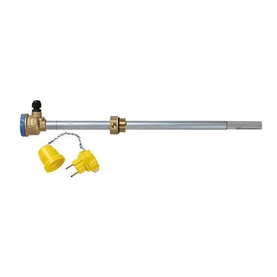
Transport und Lagerung Transport und Lagerung Das Produkt kann durch unsachgemäßen Transport und Lagerung beschä- digt werden. HINWEIS UNSACHGEMÄSSE HANDHABUNG • Stellen Sie sicher, dass während des Transports und der Lagerung des Pro- dukts die spezifizierten Umgebungsbedingungen eingehalten werden. • Benutzen Sie für den Transport die Originalverpackung. - Page 8 Produktbeschreibung Produktbeschreibung Das Produkt besteht je nach Typ aus folgenden Komponenten: „GWG 23-Ro“ und „GWG 23-T“: - Sonde - Einschraubkörper G1 - GWG-Anschlussarmatur „GWG 23-Wa“: - Sonde - Einschraubkörper G1 - Sondenkopf - Armatur für Wandmontage (gelb) Am unteren Ende der Sonde befindet sich ein geschützter Kaltleiter (PTC-Widerstand).
- Page 9 Produktbeschreibung Übersicht 4.1.1 GWG 23-Ro Das Produkt „GWG 23-Ro“ hat eine Anschlussarmatur am oberen Ende des Sondenrohrs. X = Einstellmaß Y = Kontrollmaß A. Halteband (graue Arma- tur) / Befestigungskette (gelbe Armatur) B. Kappe C. Flanschstecker-Einsatz, Typ 901 D. Armatur für Rohrmontage, Typ 904 E.
- Page 10 Produktbeschreibung 4.1.2 GWG 23-Wa Das Produkt „GWG 23-Wa“ hat einen Sondenkopf am oberen Ende des Sondenrohrs zur Verbindung der Armatur für Wandmontage Typ 905 mit dem Produkt. X = Einstellmaß Y = Kontrollmaß A. Armatur für Wandmon- tage Typ 905 B.
- Page 11 Produktbeschreibung 4.1.3 GWG 23-T Das Produkt „GWG 23-T“ hat eine verschiebbare Anschlussarmatur (Teleskop) am oberen Ende des Sondenrohres. X = Einstellmaß 20-300 mm Y = Kontrollmaß A. Schachtabdeckung B. Kappe C. Flanschstecker-Einsatz, Typ 901 D. Halteband E. Armatur für Rohrmontage, Typ 904 F.
- Page 12 Produktbeschreibung Anwendungsbeispiel(e) Funktion Das Produkt wird mit der Abfülleinrichtung des Tankfahrzeugs elektrisch ver- bunden. Der Kaltleiter wird durch diese Verbindung aufgeheizt und gibt die Befüllung frei. Wenn das Medium im Tank den Kaltleiter erreicht, ändert er seinen Widerstand. Die Steuereinrichtung des Tankfahrzeugs schließt das Absperrventil und die Befüllung wird gestoppt.
- Page 13 Produktbeschreibung Zulassungsdokumente, Bescheinigungen, Erklärungen Das Produkt „GWG 23-Ro / GWG 23-Wa / GWG 23-T“ entspricht: • EMV-Richtlinie (2014/30/EU) • Bauproduktenverordnung (EU) Nr. 305/2011 und Nr. 574/2014 (EN 13616:2004) Das Produkt „GWG 23-Ro / GWG 23-Wa“ mit der gelben Armatur für Rohr- montage oder Wandmontage entspricht zusätzlich: •...
- Page 14 Montage Montage Montage vorbereiten Wenn die Füllleitung länger als 20 m ist, bestimmen Sie das Einstellmaß X abweichend von den Einstelltabellen nach den besonderen Verhältnissen. Die hier angegebenen Einstellmaße X berücksichtigen eine Domstutzen- höhe von 100 mm für Tanks nach EN 12285-1/12285-2/DIN 6618 und 60 mm für Tanks nach DIN 6619 sowie eine Gesamtdicke des Domdeckels mit Dichtung von 20 mm.
- Page 15 Montage Elektrischer Anschluss bei GWG 23-Wa Stellen Sie sicher, dass der Leitungsübergang zum Domschacht bei Tanks für Ottokraftstoff gasdicht ist. Stellen Sie sicher, dass der Leitungsübergang zum Domschacht bei Tanks für Dieselkraftstoff und Heizöl flüssigkeitsdicht ist. Stellen Sie sicher, dass bei Verwendung des Füllrohrverschlusses (Abbil- dung 1) die Kabelverbindung etwa 10 cm länger als die Befestigungskette ist.
- Page 16 Montage A. Einführung flüssigkeitsdicht F. Füllrohrverschluss B. Anschlusskabel G. Grenzwertgeber C. Armatur für Wandmontage, Typ H. Kabelbinder 905 auf Konsole mit Bandschelle I. Füllrohrverschluss mit Anschluss an der Füllleitung oder an der für den Grenzwertgeber (nur für Schachtwand befestigt Dieselkraftstoff und Heizöl EL) D.
- Page 17 Montage 1. Verbinden Sie das Produkt und die Armatur für Wandmontage mit einem Feuchtraumkabel HO5VV-F. - Leitungsquerschnitt mindestens 2 x 1 mm², Kabellänge maximal 100 m. - Alternativ 2 x 1,5 mm² Leitungsquerschnitt, Kabellänge maximal 150 m. 2. Isolieren Sie die Aderenden auf maximal 10 mm ab. 3.
- Page 18 Montage Einstellmaß X ermitteln Wenn eine Leckschutzauskleidung montiert ist, müssen zum Einstellmaß X zusätzlich 30 mm addiert werden. • Dokumentieren Sie die Durchführung im Formblatt "Bescheinigung des Fachbetriebs". Die Sonde kann wie folgt eingestellt werden: Sondenlänge [mm] Min. X [mm] Max.
- Page 19 Montage 5.4.1 Stehende Tanks X = Einstellmaß (b - h) Y = Kontrollmaß h = Ansprechhöhe b = Gemessener Abstand zwischen Tanksohle und Oberkante Domdeckel D = Durchmesser Tanktyp Siehe Einstelltabelle ... Seite ... Nach DIN 6619:1968-07, zulässiger Füllungsgrad 97 % (V/V) Nach DIN 6619:1981-10, DIN 6619:1982-09 und DIN 6619:1989-09, ...
- Page 20 Montage 5.4.2 Zylindrisch liegende Tanks X = Einstellmaß (b - h) Y = Kontrollmaß h = Ansprechhöhe b = Gemessener Abstand zwischen Tanksohle und Oberkante Domdeckel D = Durchmesser Tanktyp Siehe Einstelltabelle ... Seite ... Nach DIN 6608-1 und DIN 6608-2 20/21 (ÖNORM C 2110) mit ≥...
- Page 21 Montage Tanktyp Siehe Einstelltabelle ... Seite ... Nach EN 12285-1 und EN 12285-2, 24-26 zulässiger Füllungsgrad 95 % (V/V) Nach EN 12285-1 und EN 12285-2, 27-29 zulässiger Füllungsgrad 97 % (V/V) Nach EN 12285-1 und EN 12285-2, 30-32 zulässiger Füllungsgrad 98 % (V/V) Nach DIN 6624 32/33 Tabelle 4: Übersicht Einstelltabellen für liegende Tanks...
- Page 22 Montage Tank Ø Raumin- Ansprech- Einstell- Kontrollmaß Y [mm] bei [mm] halt Tank/ höhe h maß X Sondenlänge [mm] [mm] abteil [m 1000 2000 1775 1795 1815 1820 1825 1830 1835 1840 2500 2255 2285 2290 2295 2300 2305 2900 2645 2665 2670...
- Page 23 Montage Tank Ø Raumin- Ansprech- Einstell- Kontrollmaß Y [mm] bei [mm] halt Tank/ höhe h maß X Sondenlänge [mm] [mm] abteil [m 1000 1000 1250 1065 1600 1320 1355 1385 1400 1410 1415 1420 2000 1725 1745 1760 1765 1770 1775 1780 1785...
- Page 24 Montage Tank Ø Raumin- Ansprech- Einstell- Kontrollmaß Y [mm] bei [mm] halt Tank/ höhe h maß X Sondenlänge [mm] [mm] abteil [m 1000 2900 2560 2585 2590 2595 Tabelle 6: Unterirdisch zylindrisch liegende Tanks mit < 0,3 m Erddeckung GWG 23-Ro / GWG 23-Wa / GWG 23-T...
- Page 25 Montage Hinweis für die Einstellmaße der Tanks nach EN 12285-1 und EN 12285-2: • Beachten Sie bezüglich des zulässigen Füllungsgrades alle am Einsatz- ort geltenden Bestimmungen, Normen und Sicherheitsvorschriften. • Die in den Tabellen enthaltenen Einstellmaße X wurden für Tanks der Klasse C berechnet.
- Page 26 Montage Tank Ø Volumen Ansprech- Einstell- Kontrollmaß Y [mm] bei [mm] Tank/ höhe h maß X Sondenlänge Kammer [mm] [mm] 1000 1900 1595 1620 1640 1660 1670 1675 1680 1685 1690 2000 1675 1700 1725 1745 1755 1760 1765 1770 1775 Tabelle 7: Zylindrisch liegende Tanks nach EN 12285-1 und EN 12285-2 mit zulässigem Füllungsgrad 95 % (V/V)
- Page 27 Montage Tank Ø Volumen Ansprech- Einstell- Kontrollmaß Y [mm] bei [mm] Tank/ höhe h maß X Sondenlänge Kammer [mm] [mm] 1000 2500 2100 2170 2195 2205 2215 2220 2225 2230 2900 2500 2550 2565 2575 2580 2585 2590 3000 2580 2635 2655 2665...
- Page 28 Montage Tank Ø Volumen Ansprech- Einstell- Kontrollmaß Y [mm] bei [mm] Tank/ höhe h maß X Sondenlänge Kammer [mm] [mm] 1000 1000 1250 1030 1070 1600 1315 1340 1360 1390 1410 1425 1440 1450 1455 1900 1640 1665 1690 1710 1720 1725 1730...
- Page 29 Montage Tank Ø Volumen Ansprech- Einstell- Kontrollmaß Y [mm] bei [mm] Tank/ höhe h maß X Sondenlänge Kammer [mm] [mm] 1000 2000 1720 1750 1775 1795 1805 1815 1820 1825 1830 1835 2500 2160 2240 2260 2275 2285 2290 2295 2300 Tabelle 8: Zylindrisch liegende Tanks nach EN 12285-1 und EN 12285-2 mit zulässigem Füllungsgrad 97 % (V/V)
- Page 30 Montage Tank Ø Volumen Ansprech- Einstell- Kontrollmaß Y [mm] bei [mm] Tank/ höhe h maß X Sondenlänge Kammer [mm] [mm] 1000 2900 2580 2635 2650 2660 2665 2670 3000 2660 2720 2740 2750 2755 2760 2765 Tabelle 8: Zylindrisch liegende Tanks nach EN 12285-1 und EN 12285-2 mit zulässigem Füllungsgrad 97 % (V/V) GWG 23-Ro / GWG 23-Wa / GWG 23-T...
- Page 31 Montage Tank Ø Volumen Ansprech- Einstell- Kontrollmaß Y [mm] bei [mm] Tank/ höhe h maß X Sondenlänge Kammer [mm] [mm] 1000 1000 1250 1010 1045 1080 1600 1330 1360 1380 1405 1425 1445 1465 1475 1480 1900 1665 1690 1715 1735 1745 1750...
- Page 32 Montage Tank Ø Volumen Ansprech- Einstell- Kontrollmaß Y [mm] bei [mm] Tank/ höhe h maß X Sondenlänge Kammer [mm] [mm] 1000 2000 1745 1775 1805 1825 1840 1845 1850 1855 1860 2500 2195 2275 2300 2315 2325 2330 2335 2340 Tabelle 9: Zylindrisch liegende Tanks nach EN 12285-1 und EN 12285-2 mit zulässigem Füllungsgrad 98 % (V/V) GWG 23-Ro / GWG 23-Wa / GWG 23-T...
- Page 33 Montage Tank Ø Volumen Ansprech- Einstell- Kontrollmaß Y [mm] bei [mm] Tank/ höhe h maß X Sondenlänge Kammer [mm] [mm] 1000 2900 2625 2680 2695 2705 2710 2715 2720 3000 2710 2770 2790 2795 2800 2805 2810 2815 Tabelle 9: Zylindrisch liegende Tanks nach EN 12285-1 und EN 12285-2 mit zulässigem Füllungsgrad 98 % (V/V) Tank Ø...
- Page 34 Montage Tank Ø Raumin- Ansprech- Ein- Kontrollmaß Y [mm] bei [mm] halt Tank/ höhe h stell- Sondenlänge -abteil [mm] maß X 1000 [mm] 1250 1040 1065 1075 1085 Tabelle 10: Liegende zylindrische Tanks nach DIN 6624 Tank Ø Raumin- Ansprech- Ein- Kontrollmaß...
- Page 35 Montage Kontrollmaß Y [mm] bei Tank Ø Raumin- Ansprech- Ein- [mm] halt Tank/ höhe h stell- Sondenlänge -abteil [mm] maß X 1000 [mm] 1000 1250 0,995/1,0 Tabelle 13: Stehende Tanks nach DIN 6623 Kontrollmaß Y [mm] bei Tank Ø Raumin- Ansprech- Ein-...
- Page 36 Montage Kontrollmaß Y [mm] bei Tank Ø Raumin- Ansprech- Ein- [mm] halt Tank/ höhe h stell- Sondenlänge [mm] maß X abteil [m [mm] 1000 2900 4584 7810 8435 11940 14980 1075 Tabelle 14: Stehende zylindrische Tanks nach DIN 6618 GWG 23-Ro / GWG 23-Wa / GWG 23-T...
- Page 37 Montage 5.4.4 Einstelltabelle für oberirdische Stahltanks Bauhöhe: 1,0 - 4,0 m 1. Messen Sie die Tankhöhe „H“. X = Einstellmaß a = Einbaumaß Y = Kontrollmaß c = Hilfsmaß z = Muffenlänge H = Tankhöhe Abbildung 2: Einbau auf Domdeckel (links), Einbau auf Tankdeckel (rechts) 2.
- Page 38 Montage Nenninhalt Tankhöhe H [m] V [m 1,25 10,0 15,0 20,0 30,0 40,0 50,0 60,0 80,0 100,0 Tabelle 15: Einbaumaß „a“ ermitteln [mm] 3. Messen Sie das Hilfsmaß „c“ oder die Muffenlänge „z“ und tragen Sie das Einstellmaß X entsprechend den Einbaugegebenheiten in Tabelle 16 ein.
-
Page 39: Montage
Montage 5.4.5 Einstelltabelle für Tanks der Haase Tank GmbH Tanktyp Tankin- Einstell- Kontrollmaß Y [mm] bei Sondenlänge halt [l] maß X 1000 [mm] Poly 25 2.500 Poly 32 3.500 Poly 35 3.500 Poly 50/51 5.000 Poly 52 5.000 Poly 61 6.000 Poly 75/76 7.500 Poly 81... - Page 40 Montage 5.4.6 Einstelltabelle für Tanks der NAU TS GmbH & Co. KG Tankin- Tank Ø Einstell- Kontrollmaß Y [mm] bei Sondenlänge halt [m³] [mm] maß X 1000 [mm] 1.970 2.130 2.260 2.500 2.680 2.840 2.990 Tabelle 18: NAU-Tanks ab Herstellung 2003 mit Außendurchmesser 660 mm und Spannring GWG 23-Ro / GWG 23-Wa / GWG 23-T...
- Page 41 Montage 5.4.7 Tanks nach DIN 4119 1. Messen Sie die Länge „l“ des Mantels. 2. Berechnen Sie die Ansprechhöhe „h“, die dem zulässigen Füllungs- grad entspricht: h = l x 0,95. 3. Messen Sie den vertikalen Abstand zwischen der Unterkante des Ein- schraubkörpers des Produkts und der Oberkante des Tankmantels (Dachecke), um das Hilfsmaß...
-
Page 42: Betrieb
1. Tauchen Sie den Kaltleiter in Flüssigkeit. 2. Dokumentieren Sie die Ergebnisse der Funktionsprüfung im “Protokoll Funktionsprüfung Grenzwertgeber“. - Das Protokoll finden Sie im Internet unter www.afriso.com. Störungsbeseitigung Störungen dürfen nur durch den Hersteller behoben werden. GWG 23-Ro / GWG 23-Wa / GWG 23-T... -
Page 43: Außerbetriebnahme Und Entsorgung
Vor einer Rücksendung Ihres Produkts müssen Sie sich mit uns in Verbin- dung setzen. Gewährleistung Informationen zur Gewährleistung finden Sie in unseren Allgemeinen Geschäftsbedingungen im Internet unter www.afriso.com oder in Ihrem Kauf- vertrag. GWG 23-Ro / GWG 23-Wa / GWG 23-T... -
Page 44: Ersatzteile Und Zubehör
Ersatzteile und Zubehör Ersatzteile und Zubehör HINWEIS UNGEEIGNETE TEILE • Verwenden Sie nur Original Ersatz- und Zubehörteile des Herstellers. Nichtbeachtung dieser Anweisung kann zu Sachschäden führen. Produkt Artikelbezeichnung Art.-Nr. Abbildung Grenzwertgeber 46009, 46118, „GWG 23-Ro“ 46126, 46185, 46013, 46127, 46115, 46121, 46116, 46123, 46117, 46125 Grenzwertgeber... - Page 45 Anhang Anhang 13.1 Bescheinigung des Fachbetriebs Hiermit bestätige ich den Einbau des Grenzwertgebers nach dieser Betriebs- anleitung. Grenzwertgeber Typ: _________________________ Einstellmaß X = __________________________ mm O Einbau mit einer Leckschutzauskleidung. => Einstellmaß X + 30 mm = _________________mm (Zugabe für Leckschutzauskleidung). Kontrollmaß...
- Page 46 Anhang Tankhersteller: ______________________________ Tanktyp: _______________________________ oder nach Norm:_________________________________ Zulassungs-Nr. des Tanks: _____________________ Fabrik-Nr.: _________________________________ Inhalt in Litern: _______________________________ GWG 23-Ro / GWG 23-Wa / GWG 23-T...
- Page 47 Anhang Fachbetrieb: __________________________________________ __________________________________________ __________________________________________ Betreiber: __________________________________________ __________________________________________ __________________________________________ Anlagenort: __________________________________________ __________________________________________ __________________________________________ __________________________________________ Datum, Unterschrift GWG 23-Ro / GWG 23-Wa / GWG 23-T...
- Page 48 Anhang 13.2 Ersatzteillieferung bei alter gewerberechtlicher Zulassung Zuordnung der alten gewerberechtlichen Zulassung bei Ersatzteillieferun- gen. 13.2.1 NAU-Tanks Tank- Bauart Gewerberechtliche Siehe Ein- größe Zulassung stelltabelle... 4.000 Einwandig 02/BAM/4.01/22/76 A Z-40.11-66 20 02/BAM/4.01/22/76 P 5.000 6.000 8.000 Doppelwandig 02/BAM/3.10/4/81 A PTB-Nr. III B/S 02/BAM/3.10/4/81 P 10.000 1627...
- Page 49 Anhang 13.2.2 Betonwerk Hörsching Tanktyp Tankinhalt [l] Prüfzeichen Siehe Ein- stelltabelle... L 4000 4.000 PA-VI 364.002 L 6000 6.000 L 8000 8.000 L 10000 10.000 L 12000 12.000 LS 2500 2.500 PA-VI 314.001 LS 4000 4.000 LS 6000 6.000 LS 8000 8.000 LS 10000 10.000...
- Page 50 Anhang 13.3 EG-Baumusterprüfbescheinigung Gültig für die Grenzwertgeber GWG 23 Ex (gelbe Armatur) GWG 23-Ro / GWG 23-Wa / GWG 23-T...
- Page 51 Anhang GWG 23-Ro / GWG 23-Wa / GWG 23-T...
- Page 52 Anhang GWG 23-Ro / GWG 23-Wa / GWG 23-T...
- Page 53 Anhang 13.4 EU-Konformitätserklärung 13.4.1 Gültig für die Grenzwertgeber GWG 23 GWG 23-Ro / GWG 23-Wa / GWG 23-T...
- Page 54 Anhang 13.4.2 Gültig für die Grenzwertgeber GWG 23 Ex (gelbe Armatur) GWG 23-Ro / GWG 23-Wa / GWG 23-T...
- Page 55 Anhang 13.5 Leistungserklärung (DoP) GWG 23-Ro / GWG 23-Wa / GWG 23-T...
- Page 56 Anhang GWG 23-Ro / GWG 23-Wa / GWG 23-T...
- Page 57 Anhang 13.6 CE-Kennzeichnung GWG 23-Ro / GWG 23-Wa / GWG 23-T...
- Page 58 Level sensor for outdoor tanks GWG 23 Type: GWG 23-Ro Type: GWG 23-Wa Type: GWG 23-T Copyright 2020 AFRISO-EURO-INDEX GmbH. All rights reserved. Lindenstraße 20 74363 Güglingen Telephone +49 7135 102-0 0123 Service +49 7135 102-211 Telefax +49 7135 102-147 info@afriso.com...
- Page 59 About these operating instructions About these operating instructions The operating instructions describe the level sensor for outdoor tanks "GWG 23-Ro / GWG 23-Wa / GWG 23-T" (also referred to as "product" in these operating instructions). These operating instructions are part of the product.
-
Page 60: Information On Safety
Information on safety Information on safety Safety messages and hazard categories These operating instructions contain safety messages to alert you to poten- tial hazards and risks. In addition to the instructions provided in these oper- ating instructions, you must comply with all directives, standards and safety regulations applicable at the installation site of the product. - Page 61 Information on safety Only the level sensors "GWG 23-Ro / GWG 23-Wa“ with the yellow fitting for pipe mounting or wall mounting have an approval for Ex zone 0 and may be connected to intrinsically safe circuits in Ex zone 0. Any use other than the application explicitly permitted in these operating instructions is not permitted and causes hazards.
- Page 62 Information on safety Qualification of personnel This product may only be mounted, commissioned, maintained and decom- missioned by a qualified, specialised company which has all required certifi- cations and which meets the following requirements: • Compliance with all directives, standards and safety regulations concern- ing handling of water-polluting substances as applicable at the installation site of the product.
-
Page 63: Transport And Storage
Transport and storage Transport and storage The product may be damaged as a result of improper transport or storage. NOTICE INCORRECT HANDLING • Verify compliance with the specified ambient conditions during transport or storage of the product. • Use the original packaging when transporting the product. •... -
Page 64: Product Description
Product description Product description Depending on the type, the product consists of the following components: "GWG 23-Ro"“and "GWG 23-T" - Probe - Screw fitting G1 - GWG level sensor connection fitting "GWG 23-Wa": - Probe - Screw fitting G1 - Probe head - Fitting for wall mounting (yellow) A protected PTC thermistor is fitted at the bottom of the probe. - Page 65 Product description Overview 4.1.1 GWG 23-Ro The product "GWG 23-Ro" features a connection fitting at the upper end of the probe tube. X = Adjustment dimension Y = Check dimension A. Strap (grey fitting) / chain strap (yellow fitting) B. cap C.
- Page 66 Product description 4.1.2 GWG 23-Wa The product "GWG 23-Wa" features a probe head at the upper end of the probe tube for connection of the fitting for wall mounting type 905 to the product. X = Adjustment dimension Y = Check dimension A.
- Page 67 Product description 4.1.3 GWG 23-T The product "GWG 23-T" features a movable connection fitting for height adjustment (telescope) at the upper end of the probe tube. X = Adjustment dimension 20-300 mm Y = Check dimension A. Manhole cover B. cap C.
- Page 68 Product description Application example(s) Function The product is electrically connected to the filling device of thre tank vehicle. This connection heats up PTC thermistor which releases the filling process. If the level in the tank is high enough for the medium to reach the PTC ther- mistor, it changes its resistance.
- Page 69 Product description Approvals, conformities, certifications The product "GWG 23-Ro / GWG 23-Wa / GWG 23-T" complies with: • EMC Directive (2014/30/EU) • Construction Products Directive (EU) No. 305/2011 und No. 574/2014 (EN 13616:2004) The product "GWG 23-Ro / GWG 23-Wa" with the yellow fitting for pipe mounting or wall mounting additionally complies with: •...
- Page 70 Mounting Mounting Preparing mounting If the filling line is longer than 20 m, do not determine the adjustment dimension X on the basis of the adjustment tables, but take into account the special conditions. The adjustment dimensions X specified take into a account a manhole socket height of 100 mm for tanks according to EN 12285-1/12285-2/DIN 6618 and 60 mm for tanks according to DIN 6619 as well as a total thickness of the manhole cover including the seal of 20 mm.
- Page 71 Mounting Electrical connection GWG 23-Wa Verify that the transition into the manhole is gas-tight in the case of tanks for petrol. Verify that the transition into the manhole is liquid-tight in the case of tanks for diesel fuel and fuel oil. ...
- Page 72 Mounting A. Transition, liquid-tight F. Filler cap B. Connection cable G. Level sensors C. Fitting for wall-mounting, H. Cable tie type 905, on console, fastened to I. Filler cap with connection for level filling line or manhole wall by sensor (only for diesel fuel and means of a clamp fuel oil EL) D.
- Page 73 Mounting 1. Connect the product and the fitting for wall mounting with moisture-proof cable HO5VV-F. - Minimum wire cross section 2 x 1 mm², maximum cable length 100 m. - Alternative: wire cross section 2 x 1.5 mm², maximum cable length 150 m.
- Page 74 Mounting Determining adjustment dimension X If a leak protection lining is mounted, you must add 30 mm to adjustment dimension X. • Document this in the form "Certificate of specialised company". The probe can be adjusted as follows: Probe length [mm] Min.
- Page 75 Mounting 5.4.1 Vertical tanks X = Adjustment dimension (b – h) Y = Check dimension h = Response level b = Measured distance between tank bottom and upper edge manhole cover D = Diameter Tank type See adjustment Page ... table ...
- Page 76 Mounting 5.4.2 Cylindrical horizontal tanks X = Adjustment dimension (b – h) Y = Check dimension h = Response level b = Measured distance between tank bottom and upper edge manhole cover D = Diameter Tank type See adjustment Page ...
- Page 77 Mounting Tank type See adjustment Page ... table ... As per EN 12285-1 and EN 12285-2, 24-27 permissible filling degree 95 % (V/V) As per EN 12285-1 and EN 12285-2, 28-30 permissible filling degree 97 % (V/V) As per EN 12285-1 and EN 12285-2, 31-33 permissible filling degree 98 % (V/V) As per DIN 6624...
- Page 78 Mounting Tank Ø Volume of Response Adjust- Check dimension Y [mm] at [mm] tank/tank level h ment probe length compart- [mm] dimen- 1000 sion X ment [m [mm] 2000 1775 1795 1815 1820 1825 1830 1835 1840 2500 2255 2285 2290 2295 2300...
- Page 79 Mounting Tank Ø Volume of Response Adjust- Check dimension Y [mm] at [mm] tank/tank level h ment probe length compart- [mm] dimen- 1000 sion X ment [m [mm] 1000 1250 1065 1600 1320 1355 1385 1400 1410 1415 1420 2000 1725 1745 1760...
- Page 80 Mounting Tank Ø Volume of Response Adjust- Check dimension Y [mm] at [mm] tank/tank level h ment probe length compart- [mm] dimen- 1000 sion X ment [m [mm] 2500 2185 2215 2220 2225 2230 2235 2900 2560 2585 2590 2595 Table 6: Underground cylindrical, vertical tanks with <...
- Page 81 Mounting Note on adjustment dimensions for tanks as per EN 12285-1 and EN 12285-2: • Respect all directives, standards and safety regulations applicable at the installation site with regard to the permissible filling degree. • The adjustment dimensions X in the tables were calculated for class C tanks.
- Page 82 Mounting Tank Ø Volume Response Adjust- Check dimension Y [mm] at [mm] tank/ level h ment probe length compart- [mm] dimen- 1000 sion X ment [m [mm] 1600 1280 1310 1325 1350 1370 1385 1400 1405 1410 1900 1595 1620 1640 1660 1670...
- Page 83 Mounting Tank Ø Volume Response Adjust- Check dimension Y [mm] at [mm] tank/ level h ment probe length compart- [mm] dimen- 1000 sion X ment [m [mm] 2000 1675 1700 1725 1745 1755 1760 1765 1770 1775 2500 2100 2170 2195 2205 2215...
- Page 84 Mounting Tank Ø Volume Response Adjust- Check dimension Y [mm] at [mm] tank/ level h ment probe length compart- [mm] dimen- 1000 sion X ment [m [mm] 2900 2500 2550 2565 2575 2580 2585 2590 3000 2580 2635 2655 2665 2670 2675 2680...
- Page 85 Mounting Tank Ø Volume Response Adjust- Check dimension Y [mm] at [mm] tank/ level h ment probe length compart- [mm] dimen- 1000 sion X ment [m [mm] 1000 1250 1030 1070 1600 1315 1340 1360 1390 1410 1425 1440 1450 1455 1900 1640...
- Page 86 Mounting Tank Ø Volume Response Adjust- Check dimension Y [mm] at [mm] tank/ level h ment probe length compart- [mm] dimen- 1000 sion X ment [m [mm] 2000 1720 1750 1775 1795 1805 1815 1820 1825 1830 1835 2500 2160 2240 2260 2275...
- Page 87 Mounting Tank Ø Volume Response Adjust- Check dimension Y [mm] at [mm] tank/ level h ment probe length compart- [mm] dimen- 1000 sion X ment [m [mm] 2900 2580 2635 2650 2660 2665 2670 3000 2660 2720 2740 2750 2755 2760 2765 Table 8: Cylindrical vertical tanks as per EN 12285-1 and EN 12285-2 with...
- Page 88 Mounting Tank Ø Volume Response Adjust- Check dimension Y [mm] at [mm] tank/ level h ment probe length compart- [mm] dimen- 1000 sion X ment [m [mm] 1000 1250 1010 1045 1080 1600 1330 1360 1380 1405 1425 1445 1465 1475 1480 1900...
- Page 89 Mounting Tank Ø Volume Response Adjust- Check dimension Y [mm] at [mm] tank/ level h ment probe length compart- [mm] dimen- 1000 sion X ment [m [mm] 2000 1745 1775 1805 1825 1840 1845 1850 1855 1860 2500 2195 2275 2300 2315 2325...
- Page 90 Mounting Tank Ø Volume Response Adjust- Check dimension Y [mm] at [mm] tank/ level h ment probe length compart- [mm] dimen- 1000 sion X ment [m [mm] 2900 2625 2680 2695 2705 2710 2715 2720 3000 2710 2770 2790 2795 2800 2805 2810...
- Page 91 Mounting Tank Ø Volume of Response Adjust- Check dimension Y [mm] at [mm] tank/tank level h ment probe length compart- [mm] dimen- 1000 sion X ment [m [mm] 1000 1250 1040 1065 1075 1085 Table 10: Horizontal, cylindrical tanks as per DIN 6624 Tank Ø...
- Page 92 Mounting Tank Ø Volume of Response Adjust- Check dimension Y [mm] at [mm] tank/tank level h ment probe length compart- [mm] dimen- 1000 sion X ment [m [mm] 2000 1500 2145 2500 11.5 2240 2900 15.0 2230 Table 12: Vertical, cylindrical tanks as per DIN 6619:1981-10, DIN 6619:1982-09 and DIN 6619:1989-09 Check dimension Y [mm] at ...
- Page 93 Mounting Tank Ø Volume of Response Adjust- Check dimension Y [mm] at [mm] tank/tank level h ment compart- [mm] dimen- probe length sion X ment [m 1000 [mm] 2000 3095 4080 4985 6465 7965 2500 4135 5115 6170 8200 2900 4584 7810...
- Page 94 Mounting 5.4.4 Adjustment table for aboveground steel tanks Height: 1.0 - 4.0 m 1. Measure the tank height „H“. X = Adjustment dimension a = Mounting dimension Y = Check dimension c = Auxiliary dimension z = Socket length H = Tank height Fig.
- Page 95 Mounting Nominal Tank height H [m] volume V 1.25 10.0 15.0 20.0 30.0 40.0 50.0 60.0 80.0 100.0 Table 15: Determining mounting dimension „a“ [mm] 3. Measure the auxiliary dimension „c“ or the socket length „z“ and enter the adjustment dimension X in accordance with the installation situa- tion in table 16.
- Page 96 Mounting 5.4.5 Adjustment table for tanks from Haase Tank GmbH Tank type Tank Adjust- Check dimension Y [mm] at probe length capacity ment 1000 dimen- sion X [mm] Poly 25 2,500 Poly 32 3,500 Poly 35 3,500 Poly 50/51 5,000 Poly 52 5,000 Poly 61...
- Page 97 Mounting 5.4.6 Adjustment table for tanks from NAU TS GmbH & Ca. KG Tank Tank Ø Adjust- Check dimension Y [mm] at probe length capacity [mm] ment 1000 [m³] dimen- sion X [mm] 1,970 2,130 2,260 2,500 2,680 2,840 2,990 Table 18: NAU tanks with year of manufacture 2003 and later with outside diam- eter 660 mm and fastening ring GWG 23-Ro / GWG 23-Wa / GWG 23-T...
- Page 98 Mounting 5.4.7 Tanks as per DIN 4119 1. Measure length „l“ of the wall. 2. Determine the response level „h“ that corresponds to the permissible filling degree: h = l x 0.95. 3. Measure the vertical distance between the lower edge of the screw fit- ting and the upper edge of the tank wall (where the roof begins) to get auxiliary dimension „c“.
-
Page 99: Operation
1. Submerge the PTC thermistor into liquid. 2. Document the results of the function test in the "Report function test pro- tection level sensor". - Visit www.afriso.com for the report. Troubleshooting Malfunctions may only be repaired by the manufacturer. GWG 23-Ro / GWG 23-Wa / GWG 23-T... -
Page 100: Decommissioning / Disposal
2. Dispose of the product. Returning the device Get in touch with us before returning your product. Warranty See our terms and conditions at www.afriso.com or your purchase contract for information on warranty. GWG 23-Ro / GWG 23-Wa / GWG 23-T... -
Page 101: Spare Parts And Accessories
Spare parts and accessories Spare parts and accessories NOTICE UNSUITABLE PARTS • Only use genuine spare parts and accessories provided by the manufac- turer. Failure to follow these instructions can result in equipment damage. Product Product designation Part no. Figure Level sensor... - Page 102 Appendix Appendix 13.1 Certificate of specialised company I hereby confirm the installation of the level sensor according to these oper- ating instructions. Level sensor type: _________________________ Adjustment dimension X = __________________ mm O Installation with leak protection lining. => Adjustment dimension X + 30 mm = _________mm (addition for leak protection lining).
- Page 103 Appendix Tank manufacturer: ___________________________ Tank type: _______________________________ or as per standard: _____________________________ Approval no. of tank: _____________________ Factory no.:_________________________________ Volume in litres: _____________________________ GWG 23-Ro / GWG 23-Wa / GWG 23-T...
- Page 104 Appendix Specialised company: __________________________________________ __________________________________________ __________________________________________ Owner/operator: __________________________________________ __________________________________________ __________________________________________ Location of system: __________________________________________ __________________________________________ __________________________________________ __________________________________________ Date, signature GWG 23-Ro / GWG 23-Wa / GWG 23-T...
- Page 105 Appendix 13.2 Spare parts delivery for systems with existing approval as per trade law Assignment of old, existing approvals in the case of spare part deliveries. 13.2.1 NAU tanks Tank Type Approval as per DIBt See adjust- size [l] trade law ment table ...
- Page 106 Appendix 13.2.2 Betonwerk Hörsching Tank type Tank capac- Certification mark See adjust- ity [l] ment table ... L 4000 4,000 PA-VI 364.002 L 6000 6,000 L 8000 8,000 L 10000 10,000 L 12000 12,000 LS 2500 2,500 PA-VI 314.001 LS 4000 4,000 LS 6000 6,000...
- Page 107 Appendix 13.3 EC Type Examination Certificate Valid for level sensor GWG 23 Ex (yellow fitting) GWG 23-Ro / GWG 23-Wa / GWG 23-T...
- Page 108 Appendix GWG 23-Ro / GWG 23-Wa / GWG 23-T...
- Page 109 Appendix GWG 23-Ro / GWG 23-Wa / GWG 23-T...
- Page 110 Appendix 13.4 EU Declaration of Conformity 13.4.1 Valid for level sensor GWG 23 GWG 23-Ro / GWG 23-Wa / GWG 23-T...
- Page 111 Appendix 13.4.2 Valid for level sensor GWG 23 Ex (yellow fitting) GWG 23-Ro / GWG 23-Wa / GWG 23-T...
- Page 112 Appendix 13.5 Declaration of Performance (DoP) GWG 23-Ro / GWG 23-Wa / GWG 23-T...
- Page 113 Appendix GWG 23-Ro / GWG 23-Wa / GWG 23-T...
- Page 114 Appendix 13.6 CE Marking GWG 23-Ro / GWG 23-Wa / GWG 23-T...
- Page 115 Appendix GWG 23-Ro / GWG 23-Wa / GWG 23-T...
Need help?
Do you have a question about the GWG 23 Series and is the answer not in the manual?
Questions and answers