
Related Manuals for Scaime eNod3-C


Summary of Contents for Scaime eNod3-C
- Page 1 Digital Transmitter User’s instructions 1/22 eNod3-C: User’s instructions NU-eNod3C-E-0911_165702-I...
- Page 2 02/08 checkweigher statistical datas presentation new inputs assignement : allow new cycle and peak 04/08 detection cycle decription modified document title modified (eNod3 => eNod3-C) 11/08 band-stop filter and automatic zero correction in checkweigher descriptions added. new hardware design logical inputs wiring examples...
-
Page 3: Table Of Contents
11.5 Checkweigher zero automatic correction ..................20 PEAK CONTROL OPERATING MODE: ............21 12.1 Non-triggered operating mode: ...................... 21 12.2 Triggered operating mode: ......................21 12.3 Management of Set-points: ......................22 12.4 Other possible outputs assignments:..................... 22 3/22 eNod3-C: User’s instructions NU-eNod3C-E-0911_165702-I... -
Page 4: General Presentation
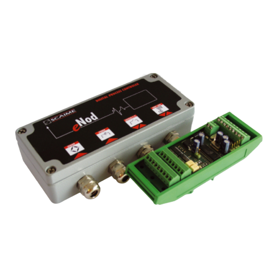
Digital Transmitter GENERAL PRESENTATION: eNod3-C provides an economic high performance solution to transform any strain gauge sensor into an intelligent digital system. includes three advanced operating modes for control of eNod3-C static and dynamic processes: Measurement transmitter. Checkweigher. Peak control. -
Page 5: General Characteristics
1000 for class IIII Minimum voltage division per verification µV scale division (∆U Maximum voltage for weighing range Minimum impedance for the load-cell Ω Maximum impedance for the load-cell 1500 Ω Value of factor P 5/22 eNod3-C: User’s instructions NU-eNod3C-E-0911_165702-I... - Page 6 Digital Transmitter Programmable functions acquisition of zero, taring, zero tracking physical or theoretical calibration slope correction non-linearity polynomial correction low-pass, band-stop and self-adaptive digital filters set points management checkweigher functioning mode peak detection functioning mode 6/22 eNod3-C: User’s instructions NU-eNod3C-E-0911_165702-I...
-
Page 7: Interfaces
4- or 6- wire load cells. eNod3-C 4-wire load cells: jumpers in place. 6-wire load cells: jumpers removed. 4/6- wire jumpers Exc+ Sens+ ON : 4 wires Exc- OFF : 6 wires Sens- Sig+ Sig- Shield 7/22 eNod3-C: User’s instructions NU-eNod3C-E-0911_165702-I... -
Page 8: Connection Of Inputs & Outputs
Digital outputs Output characteristics (opto-insulated static relays) Max current @ 40°C 0.4A Max voltage in the open state Resistance in the ON state 2 Ω Insulation voltage 2500 Vrms A light is assigned to each output. 8/22 eNod3-C: User’s instructions NU-eNod3C-E-0911_165702-I... -
Page 9: Communication Interfaces
(ON) (which is the default case on delivery). The RS232 interface is connected using Tx, Rx and REF connections on the 9-pin connector. The CAN interface is connected using the CANH, CANL and REF (not mandatory) connections on the 9-pin connector. COMMUNICATION: 9/22 eNod3-C: User’s instructions NU-eNod3C-E-0911_165702-I... -
Page 10: Modbus Rtu
3.3 CANopen® supports CANopen® communication protocol and is compliant with ‘CIA® Standard eNod3-C V301’. See the description of the frames and functions in the ‘CANopen® communication protocol’ Ref. 165 717 document. 10/22 eNod3-C: User’s instructions NU-eNod3C-E-0911_165702-I... -
Page 11: Use In Legal For Trade Applications
4.4 Specific requirements : The legal metrological software version may be displayed on the terminal. There are also some characteristics in the status related to measurements that need to be displayed on the terminal too. 11/22 eNod3-C: User’s instructions NU-eNod3C-E-0911_165702-I... -
Page 12: Calibration
The linearization formula is as follows: Corrected measurement = Meas – A (Meas) – B(Meas) – C where Meas = Current measurement The coefficients A, B and C are defined using the software calculation tool. eNodView 12/22 eNod3-C: User’s instructions NU-eNod3C-E-0911_165702-I... -
Page 13: Inputs Functioning
Stability and starting on a rising or falling edge (same as for tare control). 6.3 Functions attached to an operating mode: See corresponding sections. 13/22 eNod3-C: User’s instructions NU-eNod3C-E-0911_165702-I... -
Page 14: Outputs Functioning
- level on request: outputs state is driven by master requests on the communication bus. The activation duration can be modified. 7.3 Functions attached to an operating mode: See corresponding sections for a complete description 14/22 eNod3-C: User’s instructions NU-eNod3C-E-0911_165702-I... -
Page 15: Set Points
15/22 eNod3-C: User’s instructions NU-eNod3C-E-0911_165702-I... -
Page 16: Filters
- Self-adaptive filter : this filter can be set in cascade after previous filters. It is particularly efficient for static measurements but avoid using it in dynamic or dosing processes. The aim of this filter is to eliminate erratic measurements and to average consistent measurements. 16/22 eNod3-C: User’s instructions NU-eNod3C-E-0911_165702-I... -
Page 17: Transmitter Operating Mode
‘sampling period’ setting.Only input 2 is operational if both inputs are assigned to this function. input 10.2.3 Clear Cancels current tare (same functioning as ‘cancel tare’ command). Fig. 5 11 CHECKWEIGHER OPERATING MODE: 17/22 eNod3-C: User’s instructions NU-eNod3C-E-0911_165702-I... -
Page 18: Determination Of The Weight
O - Set point Fig. 9 Then, during a ‘stabilization time (Ts)’, the signal is highly disturbed so measurements are not taken into account. Finally, during a ‘measuring time (Tm)’ defined by either: a time value (Fig.7). 18/22 eNod3-C: User’s instructions NU-eNod3C-E-0911_165702-I... -
Page 19: Providing The Result Value
(fig. 9). As long as checkweigher result is not available (????????) or (FF FF FF FF), it is seen like a value < to set point. Set points can also be assigned to the checkweigher running total value (cumulated weight). 19/22 eNod3-C: User’s instructions NU-eNod3C-E-0911_165702-I... -
Page 20: Dynamic Zero
Interval of the zero automatic correction should be lower than checkweigher trigger level. Interval of the zero automatic correction should be in correspondence with the variation interval due to mechanical motion. The value should be lower than 10d. 20/22 eNod3-C: User’s instructions NU-eNod3C-E-0911_165702-I... -
Page 21: Peak Control Operating Mode
Regardless of the operating mode, the ‘clear’ command sets the Max and Min values to the net current value and the Peak-to-peak value to zero. Without a cycle, the ‘clear’ command sets the Max and Min and the Peak-to-peak values to zero. 21/22 eNod3-C: User’s instructions NU-eNod3C-E-0911_165702-I... -
Page 22: Management Of Set-Points
Outputs can be assigned to the set-point function (Fig. 12). Set-points can be assigned with either Max or Min or Peak-to-peak values or to the gross or net measurement. 12.4 Other possible outputs assignments: - cycle in progress. - defective measurements. 22/22 eNod3-C: User’s instructions NU-eNod3C-E-0911_165702-I...
Need help?
Do you have a question about the eNod3-C and is the answer not in the manual?
Questions and answers