
Subscribe to Our Youtube Channel
Related Manuals for Scaime eNod4-C


Summary of Contents for Scaime eNod4-C
- Page 1 Digital Process Transmitter NU-eNod4C-E-0418-196712-F.docx SCAIME SAS – Technosite Altéa – 294, Rue Georges Charpak – 74100 JUVIGNY - FRANCE Tél. : +33 (0)4 50 87 78 64 – www.scaime.com...
-
Page 2: Table Of Contents
5.5.1 Standard version ................... 26 5.5.2 Profibus version ..................27 6 CALIBRATION AND SCALE ADJUSTMENT............. 29 6.1 Physical calibration ..................29 6.2 Theoretical calibration ................. 29 6.3 Scale adjustment coefficient ..............29 6.4 Gravity correction ..................29 SCAIME Manual : NU-eNod4C-E-0418-196712-F.docx... - Page 3 11.2.4 Defective measurement: ..............37 11.2.5 Input image: ..................37 11.2.6 Level on request: ................. 37 11.2.7 Cycle in progress: ................37 11.2.8 Checkweigher result available: ............37 11.2.9 Checkweigher result out of tolerances: ..........37 SCAIME Manual : NU-eNod4C-E-0418-196712-F.docx...
- Page 4 12.1.1 Startup screens ..................40 12.1.2 Multi-eNod screens ................41 12.1.3 Main screen ..................45 12.1.4 Result displaying and storage (eNod4-C, eNod4-D) ...... 49 12.1.5 Main setup menu ................51 12.2 Checkweigher setup menu (eNod4-C) ........... 72 SCAIME Manual : NU-eNod4C-E-0418-196712-F.docx...
-
Page 5: Safety Instructions
Warning: situation potentially dangerous that could lead to death. CAUTIOUS Cautious: situation potentially dangerous that could lead to injuries. 1.1 Getting started WARNING Security provided by this product is provided for use for its intended purpose. Maintenance can only be performed by qualified staff. SCAIME Manual : NU-eNod4C-E-0418-196712-F.docx... -
Page 6: Protection
2. Disconnect the power cords from the outlets. 3. Connect the interface cables to the connectors. 3. Disconnect the interface cables from the 4. Connect the power cords into outlet. connectors. 5. Turn on the units. 4. Disconnect all cabled from the units. SCAIME Manual : NU-eNod4C-E-0418-196712-F.docx... -
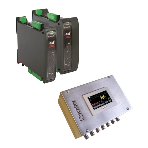
Page 7: Enod4 Product Range
4-20mA, 0-24mA, 0-20mA or 4-20mA with alarm at 3.6mA analog output current. 2.3 eNodView Software So as to configure eNod4, SCAIME provides eNodView software tool. eNodView is the software dedicated to eNod devices and digital load cell configuration from a PC. This simple graphical interface allows accessing the whole functionalities of eNod4 for a complete setting according to the application. -
Page 8: General Characteristics
3 GENERAL CHARACTERISTICS 3.1 Dimensions SCAIME Manual : NU-eNod4C-E-0418-196712-F.docx... - Page 9 SCAIME Manual : NU-eNod4C-E-0418-196712-F.docx...
-
Page 10: Characteristics
-10...+40 °C Load cell sensor Minimum input resistance Ω > sensor connection 4 or 6 wires Bridge excitation voltage Communication RS 485 Half-duplex Rate 9 600...115 200 bauds CAN 2.0A 50..1000 kbits/s PROFIBUS DP 9,600...1200 kbits/s SCAIME Manual : NU-eNod4C-E-0418-196712-F.docx... - Page 11 Metrological specifications on A3 connector input (load-cell type sensor) Input sensor range for a load cell sensor mV/V Thermal zero drift typical ppm/°C Thermal span drift typical ppm/°C Linearity deviation 0.003 % FS Conversion rate 6.25 ... 1920 meas./s SCAIME Manual : NU-eNod4C-E-0418-196712-F.docx...
-
Page 12: Legal For Trade
Maximum voltage of the weighing range Value of factor p Minimum impedance for the load cell Type of load cell(s) connection system 4-wire or 6-wire Maximum impedance for the load cell 1500 Maximal length/section measurement cable m/mm SCAIME Manual : NU-eNod4C-E-0418-196712-F.docx... - Page 13 This identifier is incremented each time a weighing result is stored and transmitted. The minimum time between two DSD recording operations is 50ms. * legal for trade use does not apply to software applicative for beltweigher (-B) and weigh feeder (-F) SCAIME Manual : NU-eNod4C-E-0418-196712-F.docx...
-
Page 14: Connections
4 CONNECTIONS SCAIME Manual : NU-eNod4C-E-0418-196712-F.docx... - Page 15 LED RS485 & Profibus / CAN NS(PRO) / NS(CAN) reset push button RS485 & Profibus / CAN LED LED sorties logiques LED alimentation & activité USB S1-S2-S3-S4 PWR-USB outputs LED power supply & USB activity LED SCAIME Manual : NU-eNod4C-E-0418-196712-F.docx...
-
Page 16: Cabling Basic Rules
Organize your wiring system into cable groups (high-voltage/power supply/signal/measurement/data cables). • Always route high-voltage and data cables in separate ducts or in separate bundles. • Install the measurement cables as close as possible to grounded surfaces (e.g. supporting beans, metal rails, steel cabinet walls). SCAIME Manual : NU-eNod4C-E-0418-196712-F.docx... -
Page 17: Power Supply Connection
4.3 Load-cell wiring Exc+ Sens+ Exc- Sens- Sig+ Sig- Shield ON: 4 wires 4/ 6 wire jumper OFF: 6 wires • 4 wires load-cell: jumpers in place (by default at delivery). • 6 wires load-cell: jumpers removed fils SCAIME Manual : NU-eNod4C-E-0418-196712-F.docx... -
Page 18: Io+ Version
Two input voltage levels are proposed for the pulse input of the speed sensor: TTL logical level or high voltage 30 V maxi level. Speed sensor power supply Speed sensor input connection IN5-TTL IN5-TTL V supply IN5-HTL IN5-HTL GNDA GNDA IN4+ IN4+ IN3+ IN3+ Iout Iout GNDA GNDA Vout Vout SCAIME Manual : NU-eNod4C-E-0418-196712-F.docx... -
Page 19: Inputs / Outputs Connections
OUT 4 An indicator light in front panel is assigned to each Output. 4.5.1 Typical connections Inputs : Connection to a detector Inputs : Connection to a push button Outputs : Possible connections Load Load Load SCAIME Manual : NU-eNod4C-E-0418-196712-F.docx... -
Page 20: Jb4 Option
4.6 JB4 option Additional resistor for special use* (not supplied) Optional overvoltage protection Corner balancing potentiometer * cut strip conductor before insertion SCAIME Manual : NU-eNod4C-E-0418-196712-F.docx... -
Page 21: Specifications
1. Press the black button with the screwdriver. 2. Stick the wire end into the relevant opening. 3. Release the pressure on the screwdriver. 4. Pull slightly the cable to check it is held tight. 7-10mm SCAIME Manual : NU-eNod4C-E-0418-196712-F.docx... -
Page 22: 220V Option
4.7 220V option Plug the supplied power cord into the AC outlet. SCAIME Manual : NU-eNod4C-E-0418-196712-F.docx... -
Page 23: Communication
(0V); the problem mentioned above can occur. The data rate that can be transmitted on different buses depends on the length of the bus. The table below shows what are the transmission rates supported by eNod4 and the corresponding maximum bus length: SCAIME Manual : NU-eNod4C-E-0418-196712-F.docx... -
Page 24: Pc Communication
Both models: eNod4 DIN and eNod4 PRO DIN can communicate with a PC using the protocols ModBus RTU or SCMbus through the USB connector accessible from the front panel. The appropriate USB driver can be downloaded from our website: http:// www.scaime.com, it is also available on CD to order from our sales department. -
Page 25: Communication Rate Selection
5.3 Communication rate selection Dipswitch selection (SW3) is accessible from the front panel. The new baud rate only is taken into account after a reset. SCAIME Manual : NU-eNod4C-E-0418-196712-F.docx... -
Page 26: Protocoles De Communication
* See protocols description in document: eNod4 software user manual. 5.5 Simultaneous functioning of communications 5.5.1 Standard version • DIN version AUX Connection AUX Connection PC Connection PC Connection eNodTouch eNodTouch PLC Connection PLC Connection PROFIBUS-DPV1 SCAIME Manual : NU-eNod4C-E-0418-196712-F.docx... -
Page 27: Profibus Version
(*) Simultaneous use of CAN or RS485 PLC with USB port can reduce performance of this interface. 5.5.2 Profibus version • DIN version AUX Connection PC Connection eNodTouch PLC Connection PROFIBUS-DPV1 SCAIME Manual : NU-eNod4C-E-0418-196712-F.docx... - Page 28 eNodTouch PLC Connection PLC Connection PROFIBUS - DPV1 PROFIBUS-DPV1 Simultaneous Profibus RS485 AUX communication yes* Profibus yes* (*) Simultaneous use of Profibus with USB port can reduce performance of this interface. SCAIME Manual : NU-eNod4C-E-0418-196712-F.docx...
-
Page 29: Calibration And Scale Adjustment
6.5 Scale interval The scale interval is the difference between 2 consecutives indications. Possible values are: 1, 2, 5, 10, 20, 50, and 100. Modification of scale interval is taking into account after a new calibration. SCAIME Manual : NU-eNod4C-E-0418-196712-F.docx... -
Page 30: Filters
This filter can be set in cascade after previous filters. It is particularly efficient for static measurements but avoid using it in dynamic or dosing processes. The aim of this filter is to eliminate erratic measurements and to average consistent measurements. SCAIME Manual : NU-eNod4C-E-0418-196712-F.docx... -
Page 31: Measurement And Status
The second, when the user wants to check the integrity of the system, allows to make the difference between a new simulated weight value and the reference. Then this difference can be compared with a dedicated maximum tolerance value. SCAIME Manual : NU-eNod4C-E-0418-196712-F.docx... -
Page 32: Checkweigher Transmitter Mode
(Fig.4). • a duration prior to an edge on an input assigned to ‘stop checkweigher cycle’ (Fig.5). Caution, only input 2 is operational if both inputs are assigned to the ‘stop checkweigher cycle’ function. SCAIME Manual : NU-eNod4C-E-0418-196712-F.docx... -
Page 33: Providing Results
This result value may be weighted by a coefficient. A value representative of the quality of the result is also determined. This value is the standard deviation of measurements acquired during the measuring time; more this value is low, the better the checkweigher result. -
Page 34: Logical Inputs
A new zero is acquired only if its value is within a range 10% of maximum capacity or 2% if eNod4-C is in legal for trade functioning mode. This new value is the useful zero value, a reset cancels it. -
Page 35: Measurement Window
Beforehand, user must acquire reference value of the load cell input by sending 'Sensor input control reference' specific command (e.g. after the device is calibrated). Note: Load cell sensor input control must be realized if no process cycle is in progress. SCAIME Manual : NU-eNod4C-E-0418-196712-F.docx... -
Page 36: Outputs Functioning
• gross measurement • net measurement • Checkweigher result • Checkweigher total running Set points and are defined by a high value, a low value and a functioning mode. Two functioning modes are possible: • Hysteresis SCAIME Manual : NU-eNod4C-E-0418-196712-F.docx... -
Page 37: Motion
Activation of outputs is triggered by master requests. When an ‘output activation’ command is received. 11.2.7 Cycle in progress: See checkweigher operating mode. 11.2.8 Checkweigher result available: See checkweigher operating mode. 11.2.9 Checkweigher result out of tolerances: Fig. 11 SCAIME Manual : NU-eNod4C-E-0418-196712-F.docx... -
Page 38: Checkweigher Result Within Tolerances
Voltage output might be set either 0-5V or 0-10V, and the current output to 4-20mA, 0-24mA, 0-20mA or 4-20mA with alarm at 3.6mA. Both output (current and voltage) might separately be enable. Settings are effective after eNod4 reset. SCAIME Manual : NU-eNod4C-E-0418-196712-F.docx... - Page 39 When analog output is assigned to “Gross measurement” or “Net measurement” its value jumps to a special error value when the internal alarm flag described in “Weighing diagnosis” § in the MEASUREMENT AND STATUS § is activated. This allows to warn about defection of the measurement chain. SCAIME Manual : NU-eNod4C-E-0418-196712-F.docx...
-
Page 40: Enodtouch - Human Machine Interface (Option)
In this case, check the wiring between eNodTouch and eNod4 (§ Electrical Powering) and check that the communication parameters of eNodTouch and eNod4 are correct (§Peripheral – Device PLC Settings). Communication error screen Connection screen Redirection screen SCAIME Manual : NU-eNod4C-E-0418-196712-F.docx... -
Page 41: Multi-Enod Screens
- Touch the Fn button of the main screen, the main menu appears. - Enter in the eNodTouch menu. - Go to the Starting Parameters screen by touching the right arrow button. Main Menu eNodTouch menu Starting parameters SCAIME Manual : NU-eNod4C-E-0418-196712-F.docx... - Page 42 According to the number of eNod settled, eNodTouch redirects to the following multi-eNod screens: Channel name Weight value Gross/Net Indicator Unit Multi eNod (2 eNod) Multi eNod (3 eNod) Multi eNod (4 eNod) Multi eNod (5 eNod) SCAIME Manual : NU-eNod4C-E-0418-196712-F.docx...
- Page 43 Main screen of eNod • To display the main screen of an eNod, touch its display area (Example for eNod n°1): • To return to multi eNod screen, touch the channel red button: Touch of channel display Multi-eNod screen SCAIME Manual : NU-eNod4C-E-0418-196712-F.docx...
- Page 44 The display module tries to recover the communication with eNod4 during 1 second, the button toggles to the « Reconnection » state. After 1 second if data from the eNod4 appears, the communication is re-established, else the button toggles to « eNod disconnected » state. SCAIME Manual : NU-eNod4C-E-0418-196712-F.docx...
-
Page 45: Main Screen
12.1.3 Main screen 12.1.3.1 Checkweigher Mode (eNod4-C) Access to result screen Last Checkweigher keyboard Result Status bar Result recorder status Checkweigher Main keyboard Status Bar SCAIME Manual : NU-eNod4C-E-0418-196712-F.docx... - Page 46 Transmitter mode • To switch from the main keyboard to the 2 keyboard touch • To enter the checkweigher quick access menu touch SCAIME Manual : NU-eNod4C-E-0418-196712-F.docx...
- Page 47 Enter in the Quick Access Menu that give access to sensor input diagnosis and allows to set applicative target weights for eNod4-C, D, F and B. Quick access can be configured to manage what is accessible in this menu for eNod4-D and F.
- Page 48 F: Start the extraction until the empty hopper level is reached. START CYCLE: C: Start Checkweigher cycle. D: Start the dosing cycle if starting eNod4-C, D, F conditions are satisfied. F: Start feeder cycle and the extraction. B: Start Belt and B dosing cycle.
-
Page 49: Result Displaying And Storage (Enod4-C, Enod4-D)
The Result screen can be displayed from the main screen with • The Result screen shows information related to the result of checkweighing cycle (eNod4-C) or Dosing cycle (eNod4-D): Last result value and statistics (Number of cycle (n), Result standard deviation (δ) and result average (µ)). - Page 50 Access to a screen displaying the table of stored results Access to a screen allowing the Transfer of stored results to an USB key, under .CSV file. Indicators Indicates the recorder running. Indicates the maximum recorder capacity (1000 results) is reached. SCAIME Manual : NU-eNod4C-E-0418-196712-F.docx...
-
Page 51: Main Setup Menu
Setup menu access can be secured by password (see § 3.5.1). In that case, the following screen is displayed: • After entering a valid password (or OLEG if you’ve forgot your password), the following menu will be displayed: eNod4-D : Dosing Modes eNod4-F : Dosing Modes eNod4-T : Transmitter Mode eNod4-C : Checkweigher Mode SCAIME Manual : NU-eNod4C-E-0418-196712-F.docx... - Page 52 Change the language of eNodTouch software Keyboard mask [Yes], [No] Enable/Disable keyboard display on main screen [Yes], [No] Enable/Disable access protection to setup menu Password 4 Char By default, “OLEG” is a master password always valid SCAIME Manual : NU-eNod4C-E-0418-196712-F.docx...
- Page 53 If there is only one eNod4 supported this function is necessarily activate. 12.1.5.3 Calibration setup When using eNod4 for legal for trade purpose, it is imperatively required to activate the legal for trade switch BEFORE any calibration procedure (cf § legal for trade switch). SCAIME Manual : NU-eNod4C-E-0418-196712-F.docx...
- Page 54 Time unit (display s, mn, h Time unit of flow rate which is displayed on main screen. flow rate) Cut-off frequency Cut-off frequency of flow rate which is displayed on main (display flow rate) screen. SCAIME Manual : NU-eNod4C-E-0418-196712-F.docx...
- Page 55 Allows creating relation between the weighing sensor and the physical values. Number of loads 1, 2, 3 Number of calibration loads used during the physical calibration. Load 1/2/3 1 – 1 000 000 Weight values corresponding to each calibration segment. SCAIME Manual : NU-eNod4C-E-0418-196712-F.docx...
- Page 56 1. Emptying the scale and press 2. Wait for the end of data acquisition. Remark : If you the operation will stop and the values will not be saved. press The latest valid calibration values will be restored. SCAIME Manual : NU-eNod4C-E-0418-196712-F.docx...
- Page 57 Remark : If you press the operation will stop and the values will not be saved. The latest valid calibration values will be restored. Theoretical calibration An automatic scaling to migrate from the factory calibration to the user calibration. SCAIME Manual : NU-eNod4C-E-0418-196712-F.docx...
- Page 58 Load cell sensitivity in mV/V at maximum capacity Span Calibration correction Span. cor 0.9 – 1.100000 Allows to adjust initial calibration Calibration g >0 (9.805470) Allows compensating the gravity difference between calibration place and using place. Use g >0 (9.805470) SCAIME Manual : NU-eNod4C-E-0418-196712-F.docx...
- Page 59 12.1.5.4 I/O setup (IO+ version only) (Available depending on version) SCAIME Manual : NU-eNod4C-E-0418-196712-F.docx...
- Page 60 Suspend cycle, Dynamic Zero, Manual emptying, Belt fault Logic [Positive]-[Negative] defines the edge (or level) that triggers input function Minimum required time of the logical inputs before their Debounced time 0 – 6553 ms activation Output 1-4 Parameters eNod4-F external totalizer (Page 2) SCAIME Manual : NU-eNod4C-E-0418-196712-F.docx...
- Page 61 When an overflow is occurred on pulses output an alarm is set. Thresholds control Allows modifying the Threshold values of the concerned outputs. Remote Control Allows fixing the level [On], [Off], of the concerned outputs. SCAIME Manual : NU-eNod4C-E-0418-196712-F.docx...
- Page 62 -MC and the highest value to +MC. Voltage Output Voltage output might be set either 0-5V or 0-10V. Current Output Current output to 4-20 mA, 0-24 mA, 0-20 mA or 4-20 mA alarm 3.6 mA. SCAIME Manual : NU-eNod4C-E-0418-196712-F.docx...
- Page 63 “defective 0 – 65535 ms alarm activation measurement alarm activation time” when it come to be active time and whatever the error conditions are during activation. 12.1.5.5 Configuration setup SCAIME Manual : NU-eNod4C-E-0418-196712-F.docx...
- Page 64 Parameter Possible Value Description Metrology Parameters SCAIME Manual : NU-eNod4C-E-0418-196712-F.docx...
- Page 65 The quotient (Maximum capacity / Scale interval) must (Available be less or equal to 6000. depending on On eNod4-C, zero tracking device must not be activated version) together with dynamic zero tracking device. On eNod4-T, C and D this mode has an effect on user calibration.
- Page 66 Data Storage Device (Available depending on version) Record ID to read Record of the ID to be read. Erase all records from the DSD memory. This is possible only when the legal for trade sealing is disabled. SCAIME Manual : NU-eNod4C-E-0418-196712-F.docx...
- Page 67 15, lower case, figures, dots and dashes only) Option « Use rotary Allows on Save automatic appending of hexadecimal representation of rotary switches switch in Name » in the Name. Byte order Byte order in Profinet exchanges ([Little Endian], [Big Endian]) SCAIME Manual : NU-eNod4C-E-0418-196712-F.docx...
- Page 68 0.10 Hz for 6.25 meas/s, 4 Hz for 400 meas/s Notch Filter parameters High & Low 0.1 to 200Hz Frequency band to attenuate with the digital Notch filter Frequency * * May not be implemented depending on eNod4 applicative version. SCAIME Manual : NU-eNod4C-E-0418-196712-F.docx...
- Page 69 Allows resetting eNod4 or making eNod4 come back to factory settings Channel name Name or rename the channel with a maximum of 4 characters Parameter Possible Value Description Sensor Input Control Parameters (Available depending on version) SCAIME Manual : NU-eNod4C-E-0418-196712-F.docx...
- Page 70 Sensor input control command and each time the weight measurement chain (sensor, connection, calibration) is modified. This command must not be realized when any process cycle that use weight is in progress. SCAIME Manual : NU-eNod4C-E-0418-196712-F.docx...
- Page 71 12.1.5.6 Functionning Mode (eNod4-C, D, F, B) • According to the eNod4 model, the following screen is displayed to select the functioning mode eNod4-C eNod4-D eNod4-B eNod4-F SCAIME Manual : NU-eNod4C-E-0418-196712-F.docx...
-
Page 72: Checkweigher Setup Menu (Enod4-C)
12.2 Checkweigher setup menu (eNod4-C) • Detailed explanations on checkweigher functioning and parameters could be found into eNod4-C manuals • The following setup menu allows modifying the parameters related to checkweigher mode. Parameter Possible Value Description Dynamic Zero parameters The ‘Dynamic zero’ function is the acquisition of a zero without Dyn. - Page 73 0 – 6553 ms result calculation During that time the signal is taken in account to calculate the Measuring time 0 – 6553 ms result. Eventually used to adjust the checkweigher result. Result correction 0.9 – 1.100000 SCAIME Manual : NU-eNod4C-E-0418-196712-F.docx...
- Page 74 Target and tolerances These functionnalities are only available in eNod4-C on versions >= 105 Target weight 0-1000000 The value to reach at the end of the checkweigher cycle Tolerance - Define the acceptable lower range for checkweigher results Tolerance +...
Need help?
Do you have a question about the eNod4-C and is the answer not in the manual?
Questions and answers