Table of Contents
Advertisement
INSTALLATION AND MAINTENANCE INSTRUCTIONS
DH100 Air Duct Smoke Detector
Before Installing
Please thoroughly read the System Sensor Guide for Proper
Use of Smoke Detectors in Duct Applications (I56-473),
which provides detailed information on detector spacing,
placement, zoning, wiring, and special applications. Cop-
ies of this manual are available from System Sensor. NFPA
Standards 72 and 90A should also be referenced for de-
tailed information.
NOTICE: This manual should be left with the owner/user
of this equipment.
IMPORTANT: This detector must be tested and maintained
regularly following NFPA 72 requirements. The detector
should be cleaned at least once a year.
Table of Contents
[1] General Description
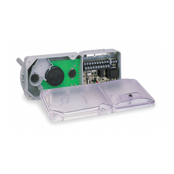
[3] Exploded View of Duct Smoke Detector Components 2
[1] General Description
An HVAC system supplies conditioned air to virtually every
area of a building. Smoke introduced into this air duct sys-
tem will be distributed to the entire building. Smoke detec-
tors designed for use in air duct systems are used to sense
the presence of smoke in the duct.
Model DH100 Air Duct Smoke Detectors are supplied as a
photoelectronic model. This smoke detection method is
combined with an efficient housing design that samples air
passing through a duct and allows detection of a develop-
ing hazardous condition. When sufficient smoke is sensed,
an alarm signal is initiated at the fire control panel monitor-
ing the detector, and appropriate action can be taken to
shut off fans, blowers, change over air handling systems,
etc. These actions can facilitate the management of toxic
smoke and fire gases throughout the areas served by the
duct system.
D100-67-00
DH100 detectors are designed to operate with 12 or 24
VDC UL listed compatible 2-wire control panels. Alarm
current must be limited to 100mA or less by the control
panel. Auxiliary relay contacts for control purposes are
not available for use with the DH100. Control must ini-
tiate from the control panel.
For testing, the alarm can be enabled by a magnet acti-
vated test switch or by the optional remote test station.
The duct smoke detector latches into alarm state when
an alarm occurs. A green LED flashes to indicate power,
a red LED signals local alarm indication, and optional
accessories offer a variety of annunciation capabilities.
The DH100 can be reset by a momentary power interrup-
tion, the reset button on the front cover, the control panel,
Page
or remote reset accessory.
1
1
[2] Limitations Of Duct Smoke Detectors
2
The National Fire Protection Association has established
2
that DUCT DETECTORS MUST NOT BE USED AS A SUB-
STITUTE FOR OPEN AREA DETECTOR PROTECTION as a
7
means of providing life safety. Nor are they a substitute for
7
early warning in a building's regular fire detection system.
8
8
System Sensor supports this position and strongly recom-
mends that the user read NFPA Standards 90A, 72, and 101.
The DH100 Air Duct Smoke Detectors are listed per UL 268A.
This device will not operate without electrical power.
Fire situations may cause an interruption of power. The
system safeguards should be discussed with your local fire
protection specialist.
This device will not sense smoke unless the ventilation sys-
tem is operating and the cover is installed.
For this detector to function properly, it MUST be installed
according to the instructions in this manual. Furthermore,
the detector MUST be protected from the elements and op-
erated within ALL electrical and environmental specifica-
tions listed in this manual. Failure to comply with these
requirements may prevent the detector from activating
when smoke is present in the air duct.
1
A Division of Pittway
3825 Ohio Avenue, St. Charles, Illinois 60174
1-800-SENSOR2, FAX: 630-377-6495
WARNING
WARNING
WARNING
WARNING
I56-1148-04
Advertisement
Table of Contents

Related Manuals for System Sensor Innovair DH100


Summary of Contents for System Sensor Innovair DH100
- Page 1 Cop- not available for use with the DH100. Control must ini- ies of this manual are available from System Sensor. NFPA tiate from the control panel. Standards 72 and 90A should also be referenced for de- tailed information.
- Page 2 [3] Figure 1: Exploded View Of Duct Detector Components FOAM GASKETS CONDUIT HOLES DETECTOR HOUSING TELESCOPING TUBE TERMINAL STRIP POWER BOARD TELESCOPING TUBE #8 SELF-TAPPING SCREW Tube Installation Chart: Supplemental Duct DETECTOR BOARD Tube Holes Width SAMPLING TUBE FILTERS 12″-14″ DETECTOR 14″-16″...
- Page 3 the inlet tube. Make sure the hole is 1″ to 2″ below the in- [5.3] Secure The Detector Housing To The Duct Slide the foam gaskets over the tube bushings as shown in let hole on the opposite side of the duct to allow for mois- Figure 3.
- Page 4 Replacement filters can be ordered from of 10 to 12 holes spaced as evenly as possible System Sensor, 3825 Ohio Ave., St. Charles, IL 60174. (Ex- across the width of the duct. haust tube/intake tube filter P/N F36-09-00) NOTE: Air currents inside the duct may cause excessive [5.6] Field Wiring...
- Page 5 For signal wiring, (the wiring between interconnected de- Before conducting these tests, notify the proper authorities tectors or from detectors to auxiliary devices), it is usually that the smoke detection system will be temporarily out of recommended that single conductor wire be no smaller service.
- Page 6 Figure 7. System wiring diagram for 2-wire duct smoke detectors (detectors powered from initiating circuit): CAUTION Do not loop wire under terminals when wiring detectors. Break wire runs to provide system supervision of connections. UL LISTED 1ST DETECTOR LAST DETECTOR COMPATIBLE 2-WIRE IN LOOP DH100 IN LOOP DH100...
- Page 7 [6.2.2] Alarm Tests [7] Detector Cleaning Procedures Notify the proper authorities that the smoke detector sys- [6.2.2.1] M02-04-00 Magnet Test 1. Place the painted surface of the magnet onto the TEST tem is undergoing maintenance, and that the system will locator on the bottom of the housing (Figure 9).
- Page 8 St. Charles, IL 60174. Please include a note describing the malfunction and for a period of three years from date of manufacture. System Sensor makes suspected cause of failure. The Company shall not be obligated to repair no other express warranty for this air duct smoke detector.
Need help?
Do you have a question about the Innovair DH100 and is the answer not in the manual?
Questions and answers