Table of Contents
Advertisement
Quick Links
Screen Filters
K
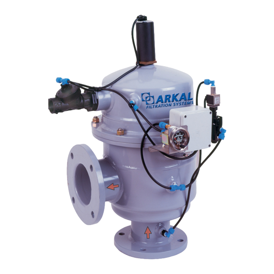
B Series
C o m p a c t , s e l f - f l u s h i n g s c r e e n f i l t e r
.eatures
<
Installed in angle position
<
Supplied in 2"- 8" inlet / outlet connections
<
Low backwash water consumption
Technical Data
Model
B-2
Metric
Connection
mm
50
diameter
Screen area
cm
2
1100
Flush flow rate at
m
3
/h
6
min. pressure
Pressure range
bar
Max.
0
C
temp.
Control voltage
Maximum .iltration .low Rate / Water Quality
Model
Filtration Grade Water
Quality
Good
Average
400 µ
Poor
Good
Average
200 µ
Poor
Good
150-100 µ
Average
Poor
Good
Average
80-50 µ
Poor
B-3
B-4
B-6
90
110
160
1100
1630
4120
6
6
20
2-10
65
9 V DC or 220 V/ 24 V AC
B-2
B-3
B-4
3
m
/h
25
40
80
25
40
80
25
40
80
25
40
80
20
35
70
15
25
40
25
40
80
15
25
40
10
20
35
10
20
35
8
18
25
6
15
20
Disc
Screen
B-8
B-2
US
225
inch
2
5240
inch
2
170
20
gpm
26
psi
0
F
B-6
B-8
B-2
gpm
130
200
110
130
200
110
130
200
110
130
200
110
90
170
88
70
130
66
130
200
110
70
150
66
60
120
44
60
120
44
50
90
35
40
60
26
Hydrocyclone
Media
B-3
B-4
B-6
3
4
6
170
253
639
26
26
88
29-145
149
9 V DC or 110 V/ 24 V AC
B-3
B-4
B-6
176
352
572
176
352
572
176
352
572
176
352
572
154
308
396
110
176
308
176
352
572
110
176
308
88
154
264
88
154
264
79
110
220
66
88
176
B-8
8
812
88
B-8
880
880
880
880
748
572
880
660
528
528
396
264
S-3
Advertisement
Table of Contents

Related Manuals for Arkal B Series


Summary of Contents for Arkal B Series
- Page 1 Screen Filters B Series C o m p a c t , s e l f - f l u s h i n g s c r e e n f i l t e r .eatures < Installed in angle position <...
- Page 2 B S S e e r r i i e e s s C o m p a c t , s e l f - f l u s h i n g s c r e e n f i l t e r Dimensions and Weights Model inch...
- Page 3 ARKAL SCREEN LINE B - SERIES Compact Self-Cleaning Screen Filter SERVICE & MAINTENANCE MANUAL...
-
Page 4: Table Of Contents
Appendix 2 - Control Loops Schematic Drawing DC ......Appendix 3 - Control Loops Schematic Drawing AC......Appendix 4 – Warranty................ALL RIGHTS RESERVED, THIS MANUAL AND THE INFORMATION CONTAINED ARE NOT ARKAL FILTRATION SYSTEMS ALLOWED TO BE USED WITHOUT WRITTEN PERMISSION FROM... -
Page 5: Introduction
B SERIES self-cleaning filter. This filter now joins the wide family of filters produced and supplied by Arkal for agriculture, municipal water and sewage systems, and all types of industrial applications. All products manufactured by Arkal are easy to install, use and service and don’t require special skills to operate them. -
Page 6: Safety Instructions
Check that all filter flange bolts are properly secured. Please note, the filter enters a flushing mode automatically, without prior warning. 10. Use original parts only when servicing the filter. 11. Arkal cannot accept responsibility for any changes or modifications to the equipment. -
Page 7: Description & Operation
Description & Operation Filter Assembly General Description (Figure 1) The B SERIES self-cleaning filter enables high quality filtration from grades of 50-400 micron from various types of water sources such as sewage, reservoirs, rivers, lakes, and wells. The B SERIES filter contains the following parts: 1. - Page 8 SERIES Filter Operation General Description (Figure 1) Water enters the filter through the “Inlet” (1). The water then reaches the fine screen (2), which purifies the flow by separating smaller particles from the water. As more water flows through, impurities build up on the fine screen. As impurities on the screen accumulate, a pressure imbalance is built up between the internal section of the fine Screen (2) and its external section.
-
Page 9: Technical Data
SERIES Technical Data Standard Features • Minimum operating pressure: 2 bar (29 psi) • Maximum operating pressure: 10 bar (145 psi) • Clean filter pressure loss: 0.1 bar (1.45 psi) • Maximum water temperature: 65°C (149°F) • Filtration range: 50-400 micron •... -
Page 10: Pressure Loss At 120 Micron
SERIES Pressure Loss At 120 Micron P (PSI) P (BAR) 220 308 1320 4400 176 264 14.5 11.6 4.35 2.91 1.45 0.73 0.05 0.58 0.04 0.02 0.145 0.01 30 40 60 80 100 200 300 1000 70 90 M /H... -
Page 11: Initial Installation & Operation
SERIES Initial Installation & Operation General The filter assembly is protectively packed with all parts assembled. Installation (Figure 2) 1. Remove the filter assembly from the carton. 2. Connect the filter assembly to the inlet line and outlet line. 3. Connect a drain pipe to the hydraulic flushing valve outlet opening (at least 40 mm diameter and not more than 5 m long) Confirm that water runs freely out of the drainpipe. - Page 12 SERIES Initial Operation 1. Gradually open the inlet valve (make sure that the outlet valve, if installed, is open). WARNING Tak e precaution while operating the filter as the filter may enter a flushing mode automatically, without prior warning. 2. Check the filter assembly and its connections for leaks. 3.
-
Page 13: Maintenance & Periodical Checks
SERIES Maintenance & Periodical Checks 9V Battery Removal & Installation (Figure 3) The 9V battery enables the electronic control unit's operation. The battery can last for 3000 flushing cycles, but should be replaced every six months. Use ONLY ALKALINE type battery. 1. -
Page 14: Control Card Removal & Installation
SERIES Control Card Removal & Installation (Figure 4) The electronic control unit contains the control card, which enables the filter's self-cleaning process. 1. Remove the 4 screws attaching the electronic control unit cover. 2. Disconnect and remove the 9V battery. 3. -
Page 15: Solenoid Removal & Installation
SERIES Solenoid Removal & Installation (Figure 5) The solenoid hydraulically controls the flushing valve's operation. 1. Remove the 4 screws attaching the electronic control unit cover, disconnect and remove the 9V battery. 2. Disconnect the solenoid control tubes. 3. Remove the fittings from the damaged solenoid. 4. - Page 16 SERIES White Black Control Tube Control Card Drain Figure 5: Solenoid Removal & Installation...
-
Page 17: Differential Pressure Indicator Removal & Installation
SERIES Differential Pressure Indicator Removal & Installation (Figure 6) The differential pressure indicator supplies data to the electronic control unit which controls the filter's self-cleaning process. 1. Disconnect the two control tubes from the differential pressure indicator. Remove the 4 screws attaching the electronic control unit cover, disconnect and remove the 9V battery. - Page 18 SERIES Hige Pressure Line (HP) Low Pressure Line (LP) Control Card Figure 6: Differential Pressure Indicator Removal & Installation...
-
Page 19: Hydraulic Piston Removal & Installation
SERIES Hydraulic Piston Removal & Installation (Figure 7) The hydraulic piston enables the linear movement of the dirt collector. 1. Close the inlet and the outlet line valves. 2. Verify that the filter is drained prior to service. 3. Disconnect the control tube from the piston assembly’s upper section. 4. - Page 20 SERIES Control Tube Hydraulic Piston Figure 7: Piston Removal & Installation...
-
Page 21: Screen Removal & Installation
SERIES Screen Removal & Installation (Figure 8) 1. Close the inlet and the outlet line valves. 2. Confirm filter draining prior to service. 3. Disconnect the control tube from the filter assembly's upper section. 4. Remove the six nuts and washers connecting both parts of the filter's housing (See Figure 8). 5. - Page 22 SERIES Control Tube Control Assembly Washer Dirt Colector Body Seal U-Ring Upper Seal (O-Ring) Screen Lower Seal (O-Ring) Screen Bearing Figure 8: Screen Removal & Installation...
-
Page 23: Periodical Checks
SERIES Periodical Checks (Figure 9) Perform yearly or periodical checks at the beginning of the season, according to the following: 1. Unscrew the lower filtering nozzle and visually check for obstructions. 2. Replace the 9V battery at the beginning of every season or every six months, refer to "9V Battery Removal &... - Page 24 SERIES Hydraulic Flushing Valve Hydraulic Piston Washer Body Seal Upper Bearing Upper Seal (O-Ring) Hydraulic Motor Screen Lower Seal (O-Ring) Filter Housing Screen Bearing Filtering Nozzle Figure 9: Periodical Checks...
-
Page 25: Troubleshooting
SERIES Troubleshooting The pressure difference between inlet and outlet is above 0.5 bar 1. Check the differential pressure indicator adjustment. 2. Verify that the line pressure matches the filter’s operational pressure. 3. Perform a flushing cycle manually, by operating the handle (turn clockwise 90°) located on the solenoid. - Page 26 SERIES Check solenoid operation by connecting white and black wires directly to the battery and immediately after, the white and red wires Solenoid clicks and Solenoid clicks but flushing Solenoid doesn't click flushing cycle starts cycle doesn't start at all (not operating) Replace the Check Inlet &...
- Page 27 SERIES Disassemble the filter and check: 1. Dirt collector rotates freely. 2. Upper bearing and screen bearing are not deformed (oval). Replace the defective Filter found serviceable part and/or release the jammed part Reassemble the The problem was not filter and operate solved during a regular the system service check.
-
Page 28: Ipb
SERIES... - Page 29 SERIES Spare Parts Description Control fitting ¼” x 6 Filtering nozzle “T” control fitting connector 6 x ¼ x 6 Lower filter housing Stud Dirt collector axis Dirt collector axis support Dirt collector Dirt collector sleeve Hydraulic motor Upper bearing U-Ring Filter cover Washer...
-
Page 30: Appendixes
SERIES Appendixes Appendix 1 - AC Controller Setting The Constant Parameters The constant parameters can be set by the internal DIP-SWITCH. The following chart describes the programming and control options of each DIP switch in the system. The DIP-SWITCH is located at the bottom right corner of the electronic board. - Page 31 SERIES Technical Data POWER SOURCES: FOR AC MODELS - 220V/50 Hz, 24V REGULATED. MAXIMUM POWER 25W. FOR DC MODELS - 12V 6 AH. DRY ALKALINE BATTERY. Connection Board (DC Model) Connection Board (AC Model)
- Page 32 SERIES The two rotary switches on the front panel are used for selecting duration and mode of flushing. The right switch selects the FLUSHING MODE and the left switch selects the FLUSHING TIME PER STATION. FLUSHING MODE FLUSHING TIME PER STATION •...
-
Page 33: Appendix 2 - Control Loops Schematic Drawing Dc
SERIES Appendix 2 - Control Loops Schematic Drawing DC Appendix 3 - Control Loops Schematic Drawing AC... -
Page 34: Appendix 4 - Warranty
30 days of discovery of such defect or failure - ARKAL FILTRATION SYSTEMS will repair or replace or refund the purchase price, at its sole option, any item proven defective in workmanship or material.
Need help?
Do you have a question about the B Series and is the answer not in the manual?
Questions and answers