Table of Contents

Subscribe to Our Youtube Channel
Related Manuals for Connect Tech COM Express Type 7+

Summary of Contents for Connect Tech COM Express Type 7+
- Page 1 COM Express® Type 7 + GPU Embedded System CTIM-00020(0.01) 2020-09-17 CONNECT TECH www.connecttech.com sales@connecttech.com CONNECT TECH INC. | 42 ARROW ROAD, GUELPH, ON N1K 1S6 CANADA | TEL: +1.836.1291 | TOLL: 800.426.8979...
-
Page 2: Table Of Contents
COM Express® Type 7 + GPU Embedded System Users Guide www.connecttech.com TABLE OF CONTENTS Table of Contents ........................2 Preface ............................4 Disclaimer ............................4 Customer Support Overview ......................4 Contact Information ......................... 4 Limited Product Warranty ....................... 5 Copyright Notice ..........................5 Trademark Acknowledgment ...................... - Page 3 COM Express® Type 7 + GPU Embedded System Users Guide www.connecttech.com Cables ............................30 Cable .............................. 30 Document: CTIM-00020 Page 3 of 30 Date: 2020-09-17 Revision: 0.01...
-
Page 4: Preface
The information contained within this user’s guide, including but not limited to any product specification, is subject to change without notice. Connect Tech assumes no liability for any damages incurred directly or indirectly from any technical or typographical errors or omissions contained herein or for discrepancies between the product and the user’s guide. -
Page 5: Limited Product Warranty
The above warranty is the only warranty authorized by Connect Tech Inc. Under no circumstances will Connect Tech Inc. be liable in any way for any damages, including any lost profits, lost savings or other incidental or consequential damages arising out of the use of, or inability to use, such product. - Page 6 COM Express® Type 7 + GPU Embedded System Users Guide www.connecttech.com Document: CTIM-00020 Page 6 of 30 Date: 2020-09-17 Revision: 0.01...
-
Page 7: Esd Warning
ESD Warning Electronic components and circuits are sensitive to ElectroStatic Discharge (ESD). When handling any circuit board assemblies including Connect Tech COM Express carrier assemblies, it is recommended that ESD safety precautions be observed. ESD safe best practices include, but are not limited to: •... -
Page 8: Introduction
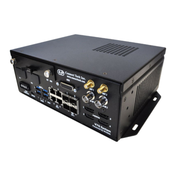
INTRODUCTION The COM Express® Type 7 + GPU Embedded System from Connect Tech combines Intel® Xeon® D (Server Class) x86 processors with high-end NVIDIA® Quadro® and Tesla® Graphics Processing Units (GPU) all into a small form factor embedded system. Choose from highest-end, highest-performance models or from low-powered models all ideal for high-end encode/decode video applications or GPGPU CUDA®... -
Page 9: Product Features And Specifications
COM Express® Type 7 + GPU Embedded System Users Guide www.connecttech.com PRODUCT FEATURES AND SPECIFICATIONS Feature COM Express Type 7 + GPU Embedded System Display Output 4x HDMI Type-A (See Part List Below) 1 Gigabit Ethernet 4x 1000BASE-T GbE Ports (RJ-45) 2x 10GBASE-SR/LR From Dual Inphi CS4223E (Dual SFP+) 10 Gigabit Ethernet Future Path to 4x 10GBASE-SR/LR From Dual Inphi CS4223E (Quad... -
Page 10: V7G Gpu System Product List
COM Express® Type 7 + GPU Embedded System Users Guide www.connecttech.com V7G GPU SYSTEM PRODUCT LIST Part COMe Type 7 CPU MXM GPU Features Operating Number Temperature NVIDIA® Quadro® 4x HDMI 0 to 55°C (RH5 to ESG701 Intel® Xeon® D1577 P5000 2x SFP 10G 90%) -
Page 11: Product Overview
COM Express® Type 7 + GPU Embedded System Users Guide www.connecttech.com PRODUCT OVERVIEW Block Diagram Document: CTIM-00020 Page 11 of 30 Date: 2020-09-17 Revision: 0.01... -
Page 12: Connector Locations
COM Express® Type 7 + GPU Embedded System Users Guide www.connecttech.com Connector Locations Document: CTIM-00020 Page 12 of 30 Date: 2020-09-17 Revision: 0.01... -
Page 13: Panel Access Locations
COM Express® Type 7 + GPU Embedded System Users Guide www.connecttech.com Panel Access Locations Document: CTIM-00020 Page 13 of 30 Date: 2020-09-17 Revision: 0.01... -
Page 14: Exterior Connector Summary
COM Express® Type 7 + GPU Embedded System Users Guide www.connecttech.com Exterior Connector Summary Connector Description Power Input Power Samtec MPT Blade Connector Micro USB B Serial Console Port via USB2.0 Quad HDMI Quad HDMI Type A Connector Quad RJ-45 Quad RJ-45 Gigabit Ethernet Connector Quad SFP+ Quad SFP+ 10 Gigabit Ethernet... -
Page 15: Detailed Feature Description
COM Express® Type 7 + GPU Embedded System Users Guide www.connecttech.com DETAILED FEATURE DESCRIPTION In COM Express Systems, the processor and chipset are implemented on the COM Express Module. This connects to the COM Express Type 7 + GPU Embedded System via a TE Board to Board Connector. The following connections are accessible on the COM Express Type 7 + GPU Embedded System from the Type 7 interface. - Page 16 COM Express® Type 7 + GPU Embedded System Users Guide www.connecttech.com Dual/Quad SFP+ Function SFP+ Location P10 Type TE Connectivity SFP+ Quad/Dual Cage Assembly 2007637-5 Mating SFP+ Plug Please reference the following KDB for supported modules. https://connecttech.com/resource-center/kdb361- xdg101-ccg070-sfp-transceiver-modules/ Note Standard Population Option is Dual SFP Quad SFP is COMe Module Specific, Optional Population SATA...
- Page 17 COM Express® Type 7 + GPU Embedded System Users Guide www.connecttech.com SMA Antenna Function Antenna Connection Location Front Panel ANT1 and ANT2 Type SMA Exterior Connector Socket Mating Standard SMA with Plug Insert (Center Pin) Note: Standard Population Covered, Optional Connector Population BNC Video IN Function SATA Storage...
- Page 18 COM Express® Type 7 + GPU Embedded System Users Guide www.connecttech.com Micro USB Type-B Function CPU Console over USB Location P13 Type Molex Micro USB Type-AB Receptacle 47590-0001 Mating Micro USB Type-B Plug USB UART Connection The UART is an FTDI based FT232RQ and will enumerate on your host system when the USB is connected, the port will remain enumerated at reboot and power loss.
- Page 19 COM Express® Type 7 + GPU Embedded System Users Guide www.connecttech.com GPIO Header Refer to section S2 switch selection for details on GPI and GPO power selection options. Function GPIO Location P18 Type HDB26 or DB15 Socket Connector Mating DB-26 or DB-15 Plug Connector. Pinout DB26 DB15 Description +3.3V...
-
Page 20: Internal Interfaces
COM Express® Type 7 + GPU Embedded System Users Guide www.connecttech.com Internal Interfaces M.2 Slot Function M.2 M-Key Slot Location P11A, P11B Type JAE Electronics M.2 Compatible Connector SM3ZS067U410AMR1000 Mating M.2 M-Key Card Edge Pinout M.2 Description M.2 Description 39 GND +3.3V 40 - 41 PCIe0 RX-... - Page 21 COM Express® Type 7 + GPU Embedded System Users Guide www.connecttech.com 31 PCIe1 RX+ 69 PEDET (pulled up to +3.3V) 32 - 70 +3.3V 33 GND 71 GND 34 - 72 +3.3V 35 PCIe1 TX- 73 GND 36 - 74 +3.3V 37 PCIe1 TX+ 75 GND 38 -...
- Page 22 COM Express® Type 7 + GPU Embedded System Users Guide www.connecttech.com +1.5V SMB_CLK PCIe TX- SMB_DATA PCIe TX+ USB D- USB D+ +3.3V +3.3V DEV_TYPE (tied to GND) +1.5V +3.3V Mounting The M.2 interface will require the following mounting Hardware for proper Hardware installation: Recommended Part Number...
-
Page 23: Switch Description
COM Express® Type 7 + GPU Embedded System Users Guide www.connecttech.com SWITCH DESCRIPTION The COM Express Type 7 + GPU Embedded System has two DIP Switch block for various on-board controls. These switches are not accessible through the Bottom Panel. S1 DIP Switch –... -
Page 24: J1 Jumper - Rtc Battery
COM Express® Type 7 + GPU Embedded System Users Guide www.connecttech.com RTC Battery The COM Express Type 7 + GPU Embedded System has one Jumpers for on-board controls. J1 Jumper – RTC Battery Function RTC Battery Enable/Clear Location J2 Pinout Position Description RTC Connected to GND... -
Page 25: On-Board Indicator Leds
COM Express® Type 7 + GPU Embedded System Users Guide www.connecttech.com ON-BOARD INDICATOR LEDS The COM Express Type 7 + GPU Embedded System has 4 Exterior indicator LEDs. Please refer to the V7G/D7G manual for further description of internal LEDs. Function Power/ Reset LEDs Location Front Panel... -
Page 26: System Bios Details
SYSTEM BIOS DETAILS The BIOS has been customized for the COM Express Type 7 + GPU Embedded System, as such modifying settings may have adverse effects on system performance and stability. Please contact Connect Tech Support prior to any BIOS modifications. -
Page 27: Mechanical Details
COM Express® Type 7 + GPU Embedded System Users Guide www.connecttech.com MECHANICAL DETAILS A complete 3D STEP Model file of COM Express Type 7 + GPU Embedded System can be downloaded here: TBD 2D Mechanical Dimensioned Drawing – Assembly and Mounting Hole Dimension are in mil. Document: CTIM-00020 Page 27 of 30 Date: 2020-09-17... -
Page 28: Hdd/Ssd Assembly
COM Express® Type 7 + GPU Embedded System Users Guide www.connecttech.com HDD/SSD Assembly Document: CTIM-00020 Page 28 of 30 Date: 2020-09-17 Revision: 0.01... -
Page 29: Chassis Mount - 2U Bracket
COM Express® Type 7 + GPU Embedded System Users Guide www.connecttech.com Chassis Mount – 2U Bracket Chassis Mount – Bottom Bracket Document: CTIM-00020 Page 29 of 30 Date: 2020-09-17 Revision: 0.01... -
Page 30: Bottom Panel
COM Express® Type 7 + GPU Embedded System Users Guide www.connecttech.com Bottom Panel CABLES The following table summarizes the COM Express Type 7 + GPU Embedded System cables available. Cable Drawing No. Part No. Description MPSS-04-16-L-06.00SR Power cable assembly Document: CTIM-00020 Page 30 of 30 Date: 2020-09-17 Revision: 0.01...
Need help?
Do you have a question about the COM Express Type 7+ and is the answer not in the manual?
Questions and answers