
Related Manuals for Daikin EWWD120MBYNN


Summary of Contents for Daikin EWWD120MBYNN
- Page 1 OPERATION MANUAL Packaged water-cooled water chillers EWWD120MBYNN EWWD180MBYNN EWWD240MBYNN EWWD280MBYNN EWWD360MBYNN EWWD440MBYNN EWWD500MBYNN EWWD520MBYNN EWWD540MBYNN...
- Page 2 (inch) provided for indoor installation and used for cooling applications. The and outlet (88.9 mm OD) EWWD units can be combined with Daikin fan coil units or air 3" • condenser water inlet 2x 3" (2x 88.9 mm OD) (inch) and outlet (88.9 mm OD)
-
Page 3: Electrical Specifications
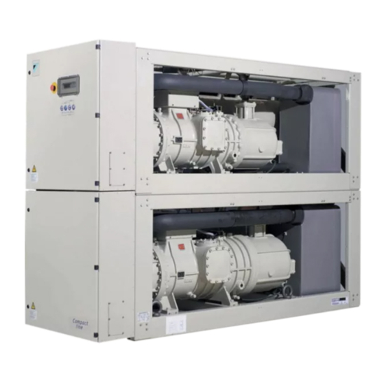
General EWWD Dimensions HxWxD 2000x2672x930 (mm) Weight 3034 3150 3346 • machine weight (kg) 3156 3281 3485 • operation weight (kg) Connections • chilled water inlet 2x 3" (2x 88.9 mm OD) (inch) and outlet • condenser water inlet 2x 3" (2x 88.9 mm OD) (inch) and outlet •... - Page 4 ESCRIPTION The EWWD water-cooled water chillers are available in 9 standard sizes. 21 20 Figure - Main components Compressor Leaving water temperature sensor Evaporator Discharge stopvalve Condenser Condensor entering water temperature sensor Switchbox Digital display controller Compressor switchbox Emergency stop Air purge condenser Power supply intake Water drain condenser...
-
Page 5: Function Of The Main Components
Function of the main components R10T Y11S Y21S S1PH S14PH S2PH S15PH Y15S Y25S Y26S Y16S (**) (***) EWWD120~280 EWWD360~540 Figure - Functional diagram Evaporator Expansion valve See A~E Condenser Suction stop valve (option) (**) - Standard (see F and G) only for EWWD120~180,360 Water out Electronic expansion valve - Dual pressure relief valve (OP03) -
Page 6: Safety Devices
Safety devices Reverse phase protector The reverse phase protectors (R*P) prevent the screw The unit is equipped with three kinds of safety devices: compressors from running in the wrong direction. If the compressors do not start, two phases of the power supply must General safety devices be inverted. -
Page 7: Before Operation
M1S,M2S ....Stepless capacity control for compressor EFORE OPERATION circuit 1, circuit 2 PE......Main earth terminal Checks before initial start-up Q1M,Q2M ....Thermal protector compressor motor R1,R2 ....Auxiliary resistance for feedback Make sure that the circuit breaker on the power supply R1F,R2F.... -
Page 8: Water Supply
Water supply PERATION Fill the water piping, taking into account the minimum water volume The EWWD120~540 units are equipped with a digital controller required by the unit. Refer to the "installation manual". offering a user-friendly way to set up, use and maintain the unit. Make sure that the water is of the quality as mentioned in the This part of the manual has a task-oriented, modular structure. - Page 9 Switching the unit on key, to enter the user password menu. key, to enter the DICN menu, also referred to as network Press the J key on the controller. menu (optional). Depending on the setting of the remote ON/OFF control key, to enter the cooling/heating menu.
- Page 10 is the percentage indication of the actual Consulting actual operational information cooling or heating capacity of the unit. Enter the readout menu. Refer to the chapter "How to enter a Press the h key to enter the next screen of the readout menu. menu"...
-
Page 11: Adjusting The Temperature Setpoint
Adjusting the temperature setpoint NOTE When a setpoint on a unit in a DICN system is set, this setpoint will be transferred to all other units. The unit provides definition and selection of four or two independent temperature setpoints. NOTE Also consult "Defining the schedule timer"... -
Page 12: Advanced Features Of The Digital Controller
Advanced features of the digital controller User settings menu This chapter gives an overview and a brief functional description of The "user settings" menu, protected by the user password, allows a the screens provided by the different menus. In the following chapter, full customization of the units. -
Page 13: Timers Menu
Timers menu To check which were the pressures of circuit 2 at the moment of shutdown. To check the actual value of the general software timers. To check which were the total amount of running hours of the compressors and the ambient temperature at the moment To check the actual value of the of shutdown. - Page 14 Tasks of the user settings menu To check the status of the changeable digital inputs. Entering the user settings menu Note that for a unit in a DICN system, the inputs apply to this unit. The user settings menu is protected by the user password, a 4-digit It will be the remote input on the master number between unit however, that will be determining...
- Page 15 Defining the thermostat settings Defining the schedule timer When automatic control mode is selected, the unit uses a thermostat To activate the screens of the schedule timer or holiday period, these to control the cooling or heating capacity. However, the thermostat first need to be enabled by changing their setting to in the parameters are not fixed and can be modified via the...
- Page 16 Also refer to the separate manual "Installation examples for a DICN Defining the network settings configuration". screen of the user settings menu allows the user to The settings on this screen of the network menu must NOTE define the network settings. be executed for all chillers connected to the system.
- Page 17 To check the actual value of the software timers, proceed as follows: Tasks of the info menu Enter the . (Refer to the chapter "How to enter a Consulting additional unit information menu" on page The controller displays the actual value of the Enter the through the main menu.
-
Page 18: Changing The User Password
The changeable relay outputs are: ROUBLESHOOTING : indicates whether the unit is running in cooling or in heating. This section provides useful information for diagnosing and correct- ing certain troubles which may occur in the unit. : indicates the status of the second evaporator pump. - Page 19 Symptom 1: The unit does not start, but the ON LED lights up Symptom 5.2: Low pressure OSSIBLE CAUSES ORRECTIVE ACTION OSSIBLE CAUSES ORRECTIVE ACTION The temperature setting is not Check the controller setpoint. Water flow to water heat exchanger Increase the water flow.
- Page 20 Symptom 13: Sensor or transmitter error Symptom 5.8: Compressor thermal protector is activated OSSIBLE CAUSES ORRECTIVE ACTION OSSIBLE CAUSES ORRECTIVE ACTION The wiring is wrong. Check if the wiring is according to Compressor motor coil temperature Compressor is not cooled sufficiently the wiring diagram.
-
Page 21: Disposal Requirements
Disposal requirements AINTENANCE Dismantling of the unit, treatment of the refrigerant, of oil and of other In order to ensure optimal availability of the unit, a number of checks parts must be done in accordance with relevant local and national and inspections on the unit and the field wiring have to be carried out legislation. - Page 22 NNEX NNEX Thermostat parameters Schedule timer example Cooling inlet water temperature control of evaporator/outlet MARCH water temperature control of evaporator The figure below shows the thermostat diagram. Fast load up Slow load up No action Slow load down To come to the schedule above following settings have to be made: Fast load down Setpoint The default value and the upper and lower limits of the thermostat...
- Page 23 III - S NNEX OFTWARE STRUCTURE Only for EWWD360~540 EWWD120~540MBYNN Operation manual Packaged water-cooled water chillers 4PW22685-1...
- Page 24 Zandvoordestraat 300, B-8400 Oostende, Belgium 4PW22685-1...
Need help?
Do you have a question about the EWWD120MBYNN and is the answer not in the manual?
Questions and answers