
Related Manuals for Di-Acro 6

Summary of Contents for Di-Acro 6
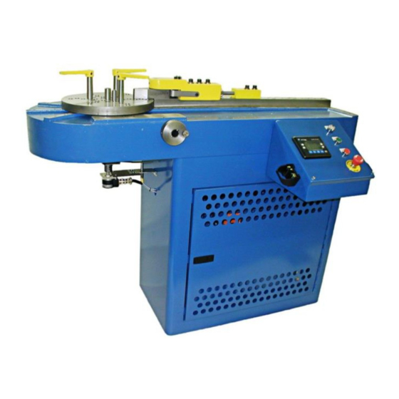
- Page 1 DI-ACRO NO. 6 & NO. 8 POWER BENDER INSTRUCTION MANUAL Toll Free: (855) 651-8948 - www.diacro.com - Fax: (651) 342-1293 12430 55 St. No. - Oak Park Heights, MN 55082 - USA...
-
Page 2: Table Of Contents
B. SAFETY INFORMATION C. SPECIFICATIONS D. INSTALLATION E. LUBRICATION F. CONTROL DESCRIPTION AND OPERATION G. SETUP & RUN – NO. 6 BENDER H. SETUP & RUN – NO. 8 BENDER CHANGING THE HOME POSITION J. TABLE ASSEMBLY K. 4” CYLINDER ASSEMBLY L. -
Page 3: Introduction
The Di-Acro Power Benders are designed to accommodate two different types of tooling. The No. 6 Bender is designed to handle tubing to 1.125” diameter (.060” wall-mild steel) and mild steel round bars up to .563” diameter. -
Page 4: Specifications
C. Specifications NO. 6 TOOLING HEAD NO. 8 TOOLING HEAD 1-1/4” OD TUBE - .060” 1-1/2” OD TUBE - .060” WALL WALL ¾” I.P.S. 1” I.P.S. 5/8” DIA SOLID ROUND 1” DIA SOLID ROUND CAPACITY (MATERIAL)* ½” SOLID SQUARE 7/8” SOLID SQUARE ¼”... -
Page 5: Installation
D. Installation During shipment, the bender may have accumulated a coating of dust or grit. Remove all dirt and rust preventative with cleaning solvent. WARNING: To prevent serious bodily injury fasten machine to floor through four holes (5/8” diameter) provided in the base of the machine. When shipped, the gauge is removed for packing purposes. -
Page 6: Lubrication
stop arms are not located as above, the group will be out of balance and may cause binding of the knurled knob. Connect electricity to a three-phase input supply making certain that the transformer and motor are connected properly for power being supplied. (208-230, or 460 VAC). Check pump rotation. - Page 7 2. HMI Screen Displays (Without Recipe Operation) The HMI panel layout is shown in the photo below. Make note of the Function Keys, Numeric Keypad, and Enter/Return key. Two screen options are provided with the standard power bender HMI. The Main Screen as shown below is used during production runs.
- Page 8 The “Manual/Homing” Screen is used to run the machine manually and to home the machine. This screen is shown below. This screen displays the Bend Value, and indicates whether the machine is Homing or Homed during the Homing procedure. ...
- Page 9 Once the desired bend has been set up, place your fingers in the two-hand safety switches located on either side of the Operator’s Console. Note that the machine will begin moving when your fingers enter these switches. It will not stop until your fingers are removed or the machine runs out of travel.
- Page 10 The machine is coded this way to combat any drift introduced by delays in the mechanical or hydraulic system. 6. Recipe Operation (If Installed) The optional Recipe Operation function allows the user to save recipes of up to 4 consecutive bends in a recipe that may be recalled when needed for production.
- Page 11 For Automatic operation with the recipe option, a recipe must be programmed and selected. Press F1 to advance to the recipe screen. The Recipe Setup Screen Display is shown below. When this screen is displayed, recipes can be programmed and selected. Press F1 to bring up the recipe selection popup.
-
Page 12: Setup & Run - No. 6 Bender
1. Turn power on. Make sure rack assembly is fully retracted into the cylinder. If you ordered the machine complete with the No. 6 tooling assembly, the machine was set up at the factory for this position to be aligned properly for this tooling assembly. - Page 13 The gap between the slide and arm should be close to even for the entire length of the slide. 6. Turn the power on and follow the manual operation instructions to rotate the pinion assembly so that the tapped holes in the pinion align with the clearance holes in the rotating arm in this position.
- Page 14 9. Set the Quik-Lok Hanger Assembly onto the rotating arm and the Quik-Lok Compression Roller Assembly onto the Slide as Shown Below. 10. Install the proper bending collar and clamp block as shown. Bolt the clamp block to the Quik-Lok hanger assembly using socket head cap screws. REV.
- Page 15 11. Adjust the Quik-Lok hanger that controls the clamp block. a. Advance the Quik-Lok hanger handle toward the radius collar so that it is in the position closest to the radius collar. b. Slide the hanger forward so that the clamp block touches the radius collar. c.
-
Page 16: Setup & Run - No. 8 Bender
NOTE: The No. 6 Bender tooling and PLC is designed to run in the counter-clockwise direction. However, it is possible to set up the machine to perform clockwise bends. If you have a need to run the bender in this manner, please contact Di-Acro for further instruction. - Page 17 6. Place the nose holder assembly on the slide as shown. Do not bolt down at this time. 7. Insert desired radius pin into center hole on mounting plate. If a radius collar is desired, insert a ½” radius pin into this hole, then slip the radius collar over it.
- Page 18 9. The mounting plate should now be rotated so that the locking pin will move away from the forming nose assembly when the mounting plate moves counter-clockwise, in a position similar to the diagram below. 10. Once the mounting plate is rotated to the proper position, power up the machine and rotate the spur pinion so that the threaded holes in it align with the counterbored holes in the mounting plate.
- Page 19 12. Adjust the nose holder assembly. a. Push the nose holder assembly so that the nose holder touches the sample material, as shown below. b. Place the Nose Holder Support onto the Slide behind the Nose Holder Assembly so that the Nose Holder Support Screw is facing the Nose Holder Assembly. Align the bolt holes with threaded holes in the slide so that the support screw can be extended to push the nose holder assembly toward the work piece.
-
Page 20: Changing The Home Position
LEDs on the proximity switch. 6. Tighten the socket head cap screw to lock the assembly in this position. 7. Home the machine per the instructions in the Operation section of this manual (page 9). - Page 21 J. Table Assembly REV. B 12/16...
- Page 22 POWER BENDER – TABLE ASSEMBLY PARTS LIST ASSEMBLY #: 8700000-060 ITEM PART NUMBER DESCRIPTION QUANTITIY 8150110-505 TABLE 8156650-300 DANGER SIGN 8991111-000 CYLINDER MOUNT 20A0508C2104 5/8-11 X 2-1/4 SHCS 5/8” LOCK WASHER 62X0508 CYLINDER ASSEMBLY 8150371-170 (SEE SECTION K) 0120646-000 SHIM 8150390-108 PINION ASSEMBLY 8150390-109...
-
Page 23: 4" Cylinder Assembly
ITEM PART NUMBER DESCRIPTION QUANTITY MATERIAL STOP ROD 8300142-007 SUPPORT 23A0516C0104 5/16-18 X ¼ SSS 62X0308 3/8 LOCK WASHER 62X0516 5/16 LOCK WASHER 8150110-800 SPACER PROXIMITY SWITCH 8150740-101 MOUNT 8150740-102 ENCODER FLEX PLATE 8150740-103 ENCODER ADAPTER 23A0X10C0104 10-24 X ¼ SSS 23A0X10C0102 10-24 X ½... -
Page 24: Base Assembly
L. Base Assembly REV. B 12/16... - Page 25 POWER BENDER – BASE ASSEMBLY PARTS LIST ASSEMBLY # 121871-000 ITEM PART NUMBER DESCRIPTION QUANTITY BASE – SUB 121871-100 ASSEMBLY 121871-200 DOOR ASSEMBLY 8150720-108 DOOR 8150720-109 HINGE 8033343-000 LATCH 20A0104C0304 ¼-20 X ¾ SHCS 62X0104 ¼ LOCK WASHER 30X0104C ¼-20 FULL NUT 21A0308C0304 3/8-16 X ¾...
-
Page 26: 6 Tooling Head Assembly
M. No. 6 Tooling Head Assembly REV. B 12/16... - Page 27 NO. 6 TOOLING HEAD ASSEMBLY – PARTS LIST ITEM PART NUMBER DESCRIPTION QUANTITY 20A0716C1104 7/16-14 X 1-1/4 SHCS 8156120-302 HOLDING PIN 8130016-970 RADIUS PIN 20A0516C0508 5/16-18 X 5/8 SHCS 8156111-371 HANGER ASSEMBLY 0308WILLIAMS 3/8 WILLIAMS WASHER WASHER 20A0308C2102 3/8-16 X 2-1/2 SHCS...
-
Page 28: Hanger Assembly
N. Hanger Assembly HANGER ASSEMBLY PARTS LIST ITEM PART NUMBER DESCRIPTION QUANTITY 8500111-300 HANDLE ROD 8120810-700 PLASTIC KNOB 19A0102X2102 ½ X 2-1/2 DOWEL PIN 5/8 X 2-1/2 DOWEL 19A0508X2102 1856111-302 HANGER WELDMENT 8920111-300 NOSE ASSEMBLY 23A0104C0104 ¼-20 X ¼ SSS 8930111-300 LINK 8156120-301... -
Page 29: Pressure Roller Assembly
O. Pressure Roller Assembly PRESSURE ROLLER ASSEMBLY PARTS LIST ITEM PART NUMBER DESCRIPTION QUANTITY 5/8 X 2-1/2 DOWEL 19A0508X2102 8156111-302 HANGER WELDMENT ROLLER ASSEMBLY 8100111-372 (SEE BELOW) 8600111-301 ROLLER HOLDER 8156111-301 ROLLER 8200120-301 ROLLER PIN 8690100-200 DRIVE FITTING 23A0104C0308 ¼-20 X 3/8 SSS 8930111-300 LINK 8156120-301... -
Page 30: 8 Tooling Head Assembly
P. No. 8 Tooling Head Assembly REV. B 12/16... - Page 31 NO. 8 TOOLING HEAD ASSEMBLY PARTS LIST ITEM PART NUMBER DESCRIPTION QUANTITY 20A0102C2102 ½-13 X 2-1/2 SHCS 20A0308C1102 3/8-16 X 1-1/2 SHCS 19A0308C1102 ½ X 1-3/4 DOWEL PIN 8158121-703 NOSE HOLDER SLIDE 20A0716C1104 7/16-14 X 1-1/4 SHCS 8158110-501 MOUNING PLATE 8158120-302 8158111-370 LOCKING PIN SMALL...
-
Page 32: Nose Holder Assembly
Q. Nose Holder Assembly NOSE HOLDER ASSEMBLY PARTS LIST ITEM PART NUMBER DESCRIPTION QUANTITY 8210510-204 SPRING 8010461-000 STEEL BALL 8158121-702 TRIGGER 8500121-701 FORMING NOSE 23A0308X0102 3/8-16 X ½ SSS 8600121-701 NOSE HOLDER 8400121-701 NOSE PIN 8310301-200 NEEDLE ROLLER 18A0104X3000 ¼ X 3 SPRING PIN 8158510-401 NOSE SPRING 21A0516C0102... -
Page 33: Gauge Group
R. Gauge Group GAUGE GROUP PARTS LIST ITEM PART NUMBER DESCRIPTION QUANTITY 8000142-007 STOP ARM STOP ROD 8151142-006 WELDMENT 8200142-007 STOP BRACKET ARM STOP BRACKET 8100142-007 ASSEMBLY 20A0516C1104 5/16-18 X 1-1/4 SHCS 20A0516C1000 5/16-18 X 1 SHCS REV. B 12/16... -
Page 34: Floor Plan
S. Floor Plan REV. B 12/16... -
Page 35: Hydraulic Diagram
T. Hydraulic Diagram REV. B 12/16... -
Page 36: Electrical Diagram
U. Electrical Diagrams THIS PAGE INTENTIONALLY LEFT BLANK Please reference the diagrams that were included with your bender. REV. B 12/16... -
Page 37: Warranty
V. Warranty and Limitation of Liability Defective parts, of a product manufactured by DI-ACRO, will be replaced or repaired at no charge for twelve (12) months following delivery to the original purchaser. Labor is included for the first 90 days. This warranty becomes void when products have not been used according to instructions furnished by DI-ACRO, nor does it cover any altered parts of unauthorized repairs.
Need help?
Do you have a question about the 6 and is the answer not in the manual?
Questions and answers