Advertisement
Quick Links
Advertisement

Related Manuals for Timberkits Stephenson's Rocket


Summary of Contents for Timberkits Stephenson's Rocket
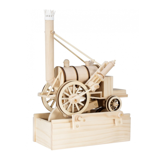
- Page 1 Stephenson’s Rocket...
- Page 2 (IT) Leggere tutte le istruzioni e guardare i diagrammi instructional videos where you (DE) Lesen sie alle anweisungen und betrachten sie die schaubilder see this symbol. www.timberkits.com (UK) Check assembly before gluing (FR) Vérifier le montage avant collage (ESP) Controlar el montaje antes de empezar a pegar (IT) Controllare l’assemblaggio prima di incollare...
- Page 3 Or visit our website for tips, advice and instructional videos. All these can be found in Resources/Advice Videos on our website.
- Page 4 9 x5 3mmx145mm 6mmx110mm 6mmx110mm 6mmx90mm 5mmx92mm 5mmx88mm 3mmx58mm x2 5mmx- 16mm 3mmx46mm x2 3mmx38 x2 2mmx34mm 3mmx 5mmx20mm 18mm 3x16mm 5mmx32mm 3mmx- 3mmx- 6mmx35mm 12mm 12mm...
- Page 5 45 x2 51 x2 43 x2 38 x2...
- Page 6 23 x2 56 x2 18 x2 46 x2 46 x2 35 x2 36 x2 29 x2...
- Page 7 4 x2 47 x2 37 x2...
- Page 8 25 x2 26 x2 53 x2 52 x2 27 x2 54 x2 40 x2 20 x2...
- Page 9 If you are mounting this model on a Battery or Electric Drive Kit please refer to the Battery or Electric Drive Kit instructions before building the model as drive pulleys need to be fitted part way through the building process 3mmx16mm 5mmx88mm protruding...
- Page 10 Line up hole with part #2 Boiler is rotated to fix #12...
- Page 11 Ensure the Firebox (#13) is parallel with the 3 x 15mm pegs on either side of rear boiler section (# 1). 30mins Use part no 16 to help ensure side rails (#15) are kept parallel 30mins...
- Page 12 Whilst the glue holding the two parts #17 is still drying, position and glue the frame built in section 3. Adjust the two parts #17 to fit against the inner rims of the frame. The bottom of the two parts #17 must be level with the underside surface of the frame as the two front axle blocks (#18) need to be glued in place at that point.
- Page 13 5mmx16mm 30mins 5mmx16mm 5mmx32mm 15mins...
- Page 14 10mins 6mmx90mm...
- Page 15 10mins 3mmx38mm 3mmx38mm 3mmx18mm 3mmx18mm Ensure the holes in 32, 9 and 33 all line up with each other. The curved side of part #34 is glued to part #33. 10mins...
- Page 16 10mins 10mins Part #34 is glued with the flat surface against part #28. 2mmx34mm 2mmx34mm...
- Page 17 It is very important that part #31 slides up and down the two 2 x 34mm rods very easily and does not stick at any point, otherwise the pistons will not work. 3mmx10mm 15mins 2mmx34mm 2mmx34mm 3mmx10mm 15mins...
- Page 18 You may want to sand the parts #40 to ensure good fit. 20mins...
- Page 19 Drop Arm Assembly from stage 6 Thread the axle through the first front axle block (#18) and then through the hole in the drop arm (#23) with no glue.
- Page 20 Then thread the axle through the friction disc (42), through the hole in the other drop arm and then through the other front axle block all with no glue. Glue part #29 so that it is in alignment with the other part #29 on the other front wheel.
- Page 21 15mins 5mmx20mm...
- Page 22 15mins 5mmx20mm...
- Page 23 3mmx10mm 3mmx10mm 3mmx10mm 3mmx10mm 3mmx10mm 3mmx10mm When fitting the parts #43 and #44 into the sides (#45) it helps to locate the pegs in the holes if you sand the end of the pegs to a point. 10mins...
- Page 24 20mins 6mmx110mm 6mmx16mm 20mins 6mmx110mm 6mmx35mm 20mins...
- Page 25 When gluing on the cranks (#46) to the shafts make sure the end of the shaft is flush/level with the surface of the cranks (#46) and that none of the shaft is protruding.
- Page 26 6mmx16mm When gluing the cranks (#46) onto the shafts, make sure that they are positioned at the angle illustrated above on opposite ends of the main drive shafts on either side of the main base unit. 6mmx16mm Slowly turn the 6mm x 35mm handle just to check that the crank assembly runs smoothly before the glue is completely dry.
- Page 27 Put a dab of glue on the shaft, on either side of the part #48, and then push up the two parts #47. Make sure they are central (as shown) and that they do not oscillate when the handle is turned. Repeat the above process with the front drive disc (# 50), making sure it is central and does not oscillate.
- Page 28 5mmx92mm Line up the front inside edge of the Rear Drop Axle (56) with the back of the Firebox (13) as shown. 25mins...
- Page 29 Push the spacer #55 so that it is level with the end of the shaft (5x92). Carefully turn the wheels to check they do not oscillate. When the wheel is in place, glue part 57 centrally on the rear axle.
- Page 30 Put a generous amount of glue in the 12mm hole in the base (as shown) and carefully push down the main shaft (#41). Push down a little at a time and keep turnng the handle until all 4 wheels start to turn freely. You will need to put glue halfway up the shaft and raise up the pivot block (#22) until it is at an angle...
- Page 31 3mmx46mm 3mmx46mm Whilst the glue is still drying on #58 and #59, follow steps 26 and 26b. Fit one side at a time. If a piston sticks at the top or bottom of its travel, either extend the length of the 3 x 46mm rod by pulling the parts #58 and #59 out by 2-3mm (if it is hitting the bottom Piston Plate) or cut off 2-3mm from the 3 x 46mm rod (if it...
- Page 32 Use part #62 in position to check face of part ¢61 is parallel to line of #62 when seen from above looking down the funnel. 15mins If you have any super glue use a drop at this stage overwise you may be holding the funnel for a long time! 30mins...
- Page 33 3mmx58mm 3mmx58mm 3mmx145mm 3mmx145mm...
- Page 34 The holes in #62 are angled. Spin the part around so that the 3mmx145mm will splay outwards towards the pistons at the back.
- Page 35 (UK) If you enjoyed building this model why not try our others. Available directly from Timberkits Ltd or from our UK, European or worldwide retail partners. Check our website to find your nearest stockist. (FR) Si vous avez apprecie construire ce modele, pourquoi ne pas en essayer d’autres. Ils sont disponibles chez Timberkits Ltd ou chez nos partenaires detaillants au Royaume Uni, en Europe et plus largement dans le monde.
- Page 36 Timberkits Limited Old Village Hall Llanbrynmair Powys, SY19 7AA 00 (44) (0) 1650 521635 timber_kits@btconnect.com www.timberkits.com Timberkits logo and all Timberkits designs are Copyright (©) 2012 all rights reserved.
Need help?
Do you have a question about the Stephenson's Rocket and is the answer not in the manual?
Questions and answers