
Related Manuals for PCM FW6

Summary of Contents for PCM FW6
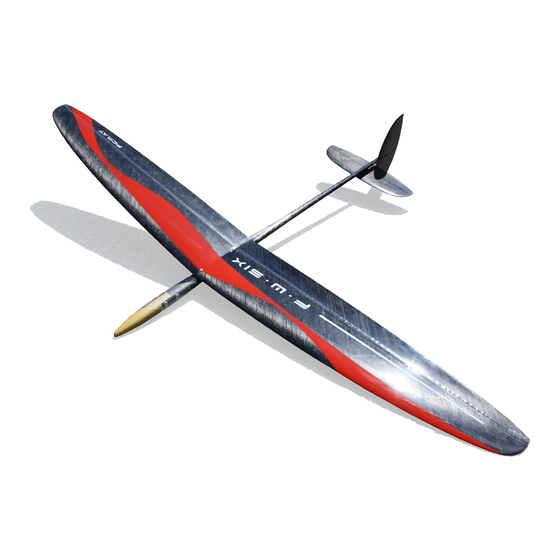
- Page 1 FW6 Building Instruction February 2015 Wing span [mm]: 1440 Wing area [dm2]: 20,5 Aspect ratio: 10,18 Take-off weight [g]: ab 240 Airfoil: Zone V2 BUILDING INSTRUCTION SAL-HLG FW6 www.pcm.at...
-
Page 2: Table Of Contents
FW6 Building Instruction February 2015 CONTENTS DATA 1. Kit – contents 2. What else do you need? 3. Electronic equipment ASSEMBLING THE MODEL 4. General 5. Wing 5.1 Controlling the ailerons 5.2 Installation of throwing blade 6. Fuselage 6.1 Radio board 6.2 Push rods for ailerons... -
Page 3: Kit - Contents
FW6 Building Instruction February 2015 DATA 1. Kit – contents Fuselage + canopy Wing Rudder and elevator CFR Radio board CFR ballast tube Lever for controlling rudder, 1 pc. Lever for controlling elevator, 1 pc. Kevlar wire for controlling rudder and elevator Steel wire for torsion springs, 2 pc. -
Page 4: Assembling The Model
For the same reason try to save weight especially when you finish and mount the stabilizer. As FW6 has developed from the Fireworks-family, you will find some pictures of Fireworks 4, FW5 and also Mini-Fireworks in the following instruction. Don’t let yourself be confused by this, the way of building described is quite the same. -
Page 5: Wing
FW6 Building Instruction February 2015 5. FW6 wing 5.1 Controlling the ailerons The levers of the ailerons are a brass tube and a brass M2 control horn. For exact fixing it into the right position a plywood template is enclosed. - Page 6 FW6 Building Instruction February 2015 For easy and accurate applying of the glue use the edge of a plastic bag. For holding the right position during the curing of the glue, prepare distance sheets. Use them under the tube and in front of the tube to place the tube as high as possible to the upper edge of the aileron.
-
Page 7: Installation Of Throwing Blade
FW6 Building Instruction February 2015 5.2. Installation of throwing blade The throwing blade has a molded adhesive flap. By this, installation is greatly simplified. Grind the gluing spots on wing and blade well and free them from sanding dust. Then fix the throwing peg with epoxy glue. -
Page 8: Fuselage
FW6 Building Instruction February 2015 6. Fuselage 6.1 Radio board First of all, push the ballast tube into the fuselage. For safety, you should only stick it when all parts are well positioned. At the moment we recommend the servo Graupner DES 281. -
Page 9: Push Rods For Ailerons
FW6 Building Instruction February 2015 6.2 Push rods for ailerons In contrast to previous models, we have increased the diameter of the pushrod and avoided bends. By this, the maximum force can be transmitted without bending of the push rods. -
Page 10: Gluing The Radio Board
FW6 Building Instruction February 2015 6.3 Gluing the radio board Before you fix the radio board in the fuselage, grind all gluing spots thoroughly. In order to gain full strength, it is absolutely necessary to fix the radio board in the fuselage! - Page 11 FW6 Building Instruction February 2015 You can fill the glue into a small plastic bag and cut a whole on one corner. By this, it will be easier to apply the glue exactly. Add carbon rovings left and right of the gluing spots for additional strength.
-
Page 12: Installation Of The Cfr-Stabs
FW6 Building Instruction February 2015 7. Installation of the CFR-stabs We use an asymmetric vertikal stab for FW6. So, first of all, please check, if you have the correct stab for left- or righthander. Vertical stab for right handers: has the hinge line on the left... -
Page 13: Connection Of The Wires
FW6 Building Instruction February 2015 Then harden the spots with super glue. Push the vertical stab (first for a test) into the oval end of the boom until ist stops. Then check, if the stabilizer is aligned correctly to the wing. -
Page 14: Ballast
FW6 Building Instruction February 2015 If you want to make the most beautiful solution, you can lead the wire out of the pylon and place the lever right behind. But you have to shorten the lever a little for that. - Page 15 FW6 Building Instruction February 2015 The hook of the ballast package is locked in the servo board. www.pcm.at...
-
Page 16: Battery Shape And Installation Of Receiver
FW6 Building Instruction February 2015 9. Battery shape and installation of receiver Depending on the size of battery and receiver different shapes of battery packs are possible. In any case we recommend to assemble the battery with tape and make a test for fitting with the receiver inside the fuselage before you solder the battery pack. -
Page 17: Settings For The First Flight
FW6 Building Instruction February 2015 10. Settings for the first flight Centre of gravity: 68-70mm (measure from the leading edge of the wing to the back) Expo at app. 50% Ailerons (measure near fuselage) Flaps negative (start, speed, fast thermal search) (measure near fuselage) - Page 18 FW6 Building Instruction February 2015 Snap Flap (measure near fuselage) Snap Flap negative (for better leveling out of the flight path at the highest point of the launch) (measure near fuselage) Rudder (measure at deepest point) Set the elevator on 0 at your first flight.
-
Page 19: Tuning Und Tips
FW6 Building Instruction February 2015 11. Tuning and tips 11.1 Flying weight and centering the masses Our long experience has shown that the take-off weight and centering of the masses are the most important factors to optimize the starting height. -
Page 20: Other
FW6 Building Instruction February 2015 OTHER 12. Check list before starting: 1. Check centre of gravity 2. Check control surfaces: Do control surfaces move in the correct direction? Check the greatest swings 3. Check reception 4. Check control surfaces before each flight.
Need help?
Do you have a question about the FW6 and is the answer not in the manual?
Questions and answers