Advertisement
Available languages
Available languages
Quick Links
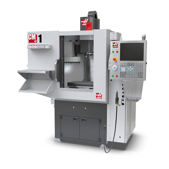
CM-1 Installation
Introducción
Eliminación del inhibidor de la oxidación
For ease of removal, first use a plastic scraper to remove most of the rust inhibitor and then use WD-40 or another
PH neutral degreaser to spray all the way covers and other non-painted surfaces that have been coated with rust
inhibitor. Let it soak for a few minutes before removing it. Then use shop towels to remove it. For thick applications of
rust inhibitor use a plastic scraper to remove it.
Important: Do not use scotch-brite or metal scrapers, these will scratch the way covers. Furthermore, to avoid any
contamination of the way cover seals with the sticky residue. Do not move any of the axes until all the rust inhibitor
has been removed.
CM - Instalación
Este procedimiento le guiará a través de la
instalación de un VMC
Herramientas requeridas:
• Nivel de maquinista de precisión,
0.0005" División
• Barra de prueba de husillo de precisión,
8" Largo
• ¾ " enchufe y trinquete
• 1-1/2" Llave
• Medida de cinta
• 0.0005" o indicador de 1 micra
• Para máquinas de 110V: Probador de
receptáculo eléctrico de 110V con
diagnóstico GFCI
• Para máquinas de 240V: Probador de
receptáculo eléctrico 240V con
diagnóstico GFCI
Page 1 of 16 pages
LAST UPDATED: 09/13/2019
Advertisement

Related Manuals for Haas CM Series


Summary of Contents for Haas CM Series
- Page 1 CM-1 Installation LAST UPDATED: 09/13/2019 CM - Instalación Introducción Este procedimiento le guiará a través de la instalación de un VMC Herramientas requeridas: • Nivel de maquinista de precisión, 0.0005" División • Barra de prueba de husillo de precisión, 8" Largo •...
- Page 2 CM-1 Installation Conexión de aire Connect the air supply at the lube panel. Note: For air requirements refer to the decal that is located on the lube cabinet door. Page 2 of 16 pages...
-
Page 3: Conexiones Eléctricas
CM-1 Installation Conexiones eléctricas Page 3 of 16 pages... - Page 4 CM-1 Installation Page 4 of 16 pages...
- Page 5 CM-1 Installation Danger: WORKING WITH ELECTRICAL SERVICES REQUIRED FOR A CNC ARE EXTREMELY HAZARDOUS. ALL POWER TO CNC MUST BE TURNED OFF LOCKOUT-TAGOUT AT THE SOURCE PRIOR TO CONNECTING THE LINE WIRES TO CNC. HOWEVER, IF THIS NOT THE CASE OR ARE NOT SURE HOW TO DO THIS, CHECK WITH APPROPIATE PERSONNEL OR OBTAIN THE NECESSARY HELP BEFORE CONTINUING.
- Page 6 CM-1 Installation Initial Control Inspection Danger: At this point, there should be no electrical connection to the machine. Electrical panel must be closed and secured. When main switch is on, there is HIGH VOLTAGE throughout the electrical panel (including the circuit boards and logic circuits) and some components operate at high temperatures.
- Page 7 CM-1 Installation After the line voltage is connected to the machine, make sure that main circuit breaker (at top-right of rear cabinet) is OFF . Remove the Lockout / Tagout and Turn ON the power at the source. Using a digital voltmeter and appropriate safety procedures: 1-Phase Machines: Measure the AC voltage...
- Page 8 CM-1 Installation Transformer T5 supplies 24VAC used to power the main contactor. There are two versions of this transformer for use on a 240 and 400V machines. The 240V transformer has two input connectors located about two inches from the transformer, which allow it to be connected to either 180-220V or 221-240V.
- Page 9 CM-1 Installation Electrical power must be phased properly to avoid damage to your equipment. The Power Supply Assembly PC board incorporates a "Phase Detect" circuit with neon indicators. When the orange neon is lit (NE5), the phasing is incorrect. If the green neon is lit (NE6), the phasing is correct. If both neon indicators are lit, you have a loose wire;...
- Page 10 CM-1 Installation Eliminación de soportes de envío Soporte Pendent • Retire los dos tornillos superiores que sujetan la pendiente en la posición bloqueada • Gira el plumón para acceder a los dos tornillos situados cerca del trasero colgante y retíralos. Soporte de guía de cable •...
- Page 11 CM-1 Installation Nivelación de máquinas • Limpie y trote la mesa para que se centre en la máquina. • Coloque el nivel de precisión de modo que el vial largo sea paralelo al eje X. Utilice los slots en T como referencia •...
- Page 12 CM-1 Installation Barrido del husillo • Fijar indicador al cabezal de la espinaca • Coloque la mesa y el indicador de tal forma que cuando se barre el husillo mide un círculo 10" en diámetro • Tome un bloque 1-2-3 y colóquelo en la mesa trotar el husillo hacia abajo y cero el indicador en la posición 1 •...
-
Page 13: Funcionamiento De La Máquina
CM-1 Installation Funcionamiento de la máquina Page 13 of 16 pages... - Page 14 CM-1 Installation Operación del husillo de prueba • Ejecutar spindle Run en el programa 009221 ubicada en la carpeta 009000. • En el caso de ruido inusual del husillo, ejecute una prueba de vibración Para obtener una guía sobre cómo realizar una prueba de vibración del husillo, consulte: ANÁLISIS DE VIBRACIÓN - INTERFAZ ETHERNET...
- Page 15 CM-1 Installation Funcionamiento de la cámara Wifi Si su máquina viene con la opción de cámara Wifi, consulte el siguiente enlace para obtener instrucciones de instalación: OPCIÓN DE CÁMARA WI-FI - INSTALACIÓN HrT100 Operación Si su máquina viene con una mesa giratoria HRT 100, consulte el siguiente enlace para obtener instrucciones de instalación: PLEASE ADD LINK OR LINK TEXT.
- Page 16 ▪ Mientras las cerraduras están en tratar de abrir las puertas ▪ El husillo no debe dejar de girar, pero si el husillo se detiene, póngase en contacto con Haas para obtener asistencia Page 16 of 16 pages...
Need help?
Do you have a question about the CM Series and is the answer not in the manual?
Questions and answers