Table of Contents
Advertisement
Quick Links
Advertisement
Table of Contents

Related Manuals for EqualLogic PS Series


Summary of Contents for EqualLogic PS Series
- Page 1 Hardware Maintenance Hardware Maintssss...
- Page 2 Possession, use, or copying of the documentation or the software described in this publication is authorized only under the license agreement. EqualLogic, Inc. will not be held liable for technical or editorial errors or omissions contained herein. Information in this document is subject to change.
-
Page 3: Table Of Contents
Table of Contents Preface ......................v Introduction to PS Series Storage Arrays ...........1 Steps for Setting Up and Using an Array ...........2 Step 1. Set Up the Array Hardware Configuration ........3 A. Unpack Shipping Box and Gather Required Hardware ..3 B. Mount Array in a Rack ............8 C. -
Page 5: Preface
Preface This QuickStart describes how to set up EqualLogic PS Series model 50E to 400E storage array hardware and create a PS Series group—a self-managing, storage area network (SAN) that is affordable and easy to use, regardless of scale. After setting up the group, see the PS Series Group Administration manual for information about managing the group. - Page 6 Release Notes. Provides the latest information about PS Series storage arrays. • QuickStart. Describes how to set up the storage array hardware and create a PS Series group. Be sure to use the manual for your array model. • Group Administration. Describes how to use the Group Manager graphical user interface (GUI) to manage a PS Series group.
- Page 7 Preface The QuickStart and Hardware Maintenance manuals are printed and shipped with the product. They are also located on the PS Series documentation CD-ROM that is shipped with the product, along with the Group Administration and CLI Reference manuals and the Group Manager online help.
-
Page 9: Introduction To Ps Series Storage Arrays
With intelligent, automated management and fast, flexible scalability, PS Series arrays greatly reduce storage acquisition and management costs. By grouping together one or more PS Series arrays connected to an IP network, you can create a PS Series group—a highly-scalable iSCSI SAN with a shared pool of storage space. -
Page 10: Steps For Setting Up And Using An Array
Management overhead remains the same, regardless of the group size. Steps for Setting Up and Using an Array To start using your PS Series array: Step 1. Set up the array hardware configuration. -
Page 11: Step 1. Set Up The Array Hardware Configuration
Product returns will be accepted only in the original packaging or in authorized packaging obtained from your PS Series support provider. - Page 12 PS Series 50E to 400E QuickStart Step 1. Set Up the Array Hardware Configuration Ensure that the shipping box includes all the components required for installation, as shown in the following figure and described in the table Storage Array Shipping Box Contents.
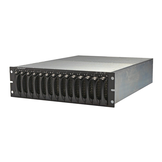
- Page 13 PS Series 50E to 400E QuickStart Step 1. Set Up the Array Hardware Configuration Storage Array Shipping Box Contents Component Description Storage array chassis The 3U unit contains one or two control modules, two power supplies, two fan trays, and slots for up to 14 disks.
- Page 14 Storage Array Shipping Box Contents (Continued) Component Description Documentation and Printed documentation includes the PS Series QuickStart, CD-ROMs Hardware Maintenance, Release Notes, and SAN setup poster. The Group Administration and CLI Reference manuals and the Group Manager online help are on the documentation CD-ROM, along with the QuickStart and Hardware Maintenance manuals.
- Page 15 Cage nuts Enable you to mount an array in a rack with square holes. The environmental, power, and physical requirements for PS Series 50E to 400E storage arrays are described in the following table. Storage Array Requirements...
-
Page 16: Mount Array In A Rack
Step 1. Set Up the Array Hardware Configuration B. Mount Array in a Rack A PS Series array must be mounted in a two-pole or four-pole 19” rack. Be sure there is sufficient space for air flow in front of and behind the rack and the room has proper ventilation. - Page 17 PS Series 50E to 400E QuickStart Step 1. Set Up the Array Hardware Configuration Mounting in a Four-Pole Rack...
-
Page 18: Install Disks Or Blank Carriers
PS Series 50E to 400E QuickStart Step 1. Set Up the Array Hardware Configuration C. Install Disks or Blank Carriers Follow these rules for handling PS Series array disks: • Do not remove a disk from its plastic carrier or you will void your warranty and support contract. -
Page 19: Connect Power Cables For Grounding
PS Series 50E to 400E QuickStart Step 1. Set Up the Array Hardware Configuration D. Connect Power Cables for Grounding A PS Series array includes two power supplies. It is recommended that you connect both power supplies to different power sources, preferably on separate circuits. -
Page 20: Connect Array To A Network Switch
Step 1. Set Up the Array Hardware Configuration E. Connect Array to a Network Switch A PS Series array includes one or two control modules and can have one to three network connections. Only one control module is active (actively serving I/O) at one time. - Page 21 Flow Control Enable Flow Control on each switch port and NIC that handles enabled on switches iSCSI traffic. PS Series arrays will correctly respond to and NICs Flow Control. Unicast storm Disable unicast storm control on each switch that handles iSCSI control disabled on traffic, if the switch provides this feature.
- Page 22 PS Series 50E to 400E QuickStart Step 1. Set Up the Array Hardware Configuration Recommendations for connecting network cables are as follows: • Connect Ethernet interfaces in the following order: PORT 0, PORT 1, and PORT 2. • Distribute network connections across control modules and network switches.
-
Page 23: Turn On Power To Array And Check Leds
PS Series 50E to 400E QuickStart Step 1. Set Up the Array Hardware Configuration F. Turn on Power to Array and Check LEDs Before turning on power, be sure the array is at room temperature. If an error message or LED indicates a problem, contact the support provider for your PS Series array. - Page 24 PS Series 50E to 400E QuickStart Step 1. Set Up the Array Hardware Configuration Front Panel LED Descriptions (Continued) Array LEDs Color Description No power or normal condition. WARN One or more of the following has occurred: • RAID set is degraded but still functioning.
- Page 25 PS Series 50E to 400E QuickStart Step 1. Set Up the Array Hardware Configuration Disk LED Descriptions Disk LEDs Color Description Left No power or error condition Green Power. Right No power or normal condition. Error condition. Flashing Disk activity.
- Page 26 PS Series 50E to 400E QuickStart Step 1. Set Up the Array Hardware Configuration Power Supply LED Descriptions Power Supply LEDs Color Description Left (location may differ on No power or error condition. some power supplies) Orange Input power good (AC).
-
Page 27: Connect Array To A Console Terminal
PS Series 50E to 400E QuickStart Step 1. Set Up the Array Hardware Configuration G. Connect Array to a Console Terminal Set up a serial connection between the array and a console terminal (or a computer running a terminal emulator) to run the utility and add the array to a group. -
Page 28: Step 2. Configure The Array And Create A Group
PS Series group with the array as the first member. The utility prompts for the array’s network configuration and the group configuration, including the group IP address. - Page 29 PS Series 50E to 400E QuickStart Step 2. Configure the Array and Create a Group Group Configuration Prompt Description Group name Name of the group (up to 54 characters). Valid characters include letters, number, and dashes. The first character must be a letter or number.
- Page 30 PS Series 50E to 400E QuickStart Step 2. Configure the Array and Create a Group An example of running the utility is shown next. There may be a short setup delay after entering the group IP address as the array searches the network.
-
Page 31: Step 3. Set The Raid Policy
PS Series 50E to 400E QuickStart Step 3. Set the RAID Policy Step 3. Set the RAID Policy After you create the group, use the Group Manager GUI or CLI to set the RAID policy for the member. This will automatically configure the disks according to the RAID policy, with the appropriate number of spare disks. -
Page 32: Using The Gui To Set The Raid Policy
The Group Summary window appears. Note: To obtain Group Manager help from the EqualLogic website, click Tools in the bottom left corner of the GUI and then click... - Page 33 PS Series 50E to 400E QuickStart Step 3. Set the RAID Policy Click and the Configure Member – General Settings dialog box appears. Configure Member – General Settings Enter an optional member description and click . The Configure Member –...
- Page 34 PS Series 50E to 400E QuickStart Step 3. Set the RAID Policy Select the RAID policy for the member. The pool capacity values in the dialog box table will change, depending on the selected RAID policy. For example, in the preceding dialog box, selecting RAID- 50 provides an estimated capacity of 5.24 TB.
-
Page 35: Using The Cli To Set The Raid Policy
PS Series 50E to 400E QuickStart Step 3. Set the RAID Policy Group Summary – Completed Member Configuration Using the CLI to Set the RAID Policy To access the CLI, establish a telnet or SSH connection to the group IP address or use a serial connection to the array, as described in Step 1-G on page 19. -
Page 36: Step 4. Create A Volume
Note: Thin provisioning is an advanced volume feature and may not be appropriate for all environments. See the PS Series Group Administration manual for detailed information. - Page 37 PS Series 50E to 400E QuickStart Step 4. Create a Volume • Access controls – Access control records are used to restrict volume access to hosts that supply the correct credentials. By default, no host can access a volume. A host must match a record in order to access a volume. You can restrict access according to the following: –...
-
Page 38: Using The Gui To Create A Volume
PS Series 50E to 400E QuickStart Step 4. Create a Volume Using the GUI to Create a Volume To start the GUI, specify the group IP address in a Web browser. When prompted, log in to the group by entering the... - Page 39 PS Series 50E to 400E QuickStart Step 4. Create a Volume Create Volume – Space Reserve Enter the following information: • Volume size. Be sure to specify the correct unit of measurement. • Thin-provisioning setting. If selected, slider bars appear, enabling you to specify the minimum volume reserve, the in-use space warning value, and the maximum in-use space value for the thin-provisioned volume.
- Page 40 PS Series 50E to 400E QuickStart Step 4. Create a Volume Create Volume – iSCSI Access Specify the IP address, CHAP user name, or iSCSI initiator name to which the volume will be restricted. In the previous dialog box, volume access is restricted to IP address 172.17.1.40.
- Page 41 PS Series 50E to 400E QuickStart Step 4. Create a Volume Create Volume – Summary Once you create a volume, you can create snapshots of the volume or perform other tasks. The following Group Summary window shows a group with volumes and snapshots.
-
Page 42: Using The Cli To Create A Volume
PS Series 50E to 400E QuickStart Step 4. Create a Volume Using the CLI to Create a Volume To access the CLI, establish a telnet or SSH connection to the group IP address or use a serial connection to the array, as described in Step 1-G on page 19. When... -
Page 43: Step 5. Connect To The Volume From A Host System
Step 5. Connect to the Volume from a Host System Step 5. Connect to the Volume from a Host System A PS Series group volume is seen on the network as an iSCSI target. When you create a volume, its iSCSI target name is generated automatically. An example of... -
Page 44: Advanced Operations And More Information
Advanced Operations and More Information Advanced Operations and More Information After getting started, you can customize a PS Series group and also utilize the full set of product features and host-based solutions. You can also obtain technical support. For more information, see Product Documentation and Technical Support on page vi. - Page 45 PS Series 50E to 400E QuickStart Advanced Operations and More Information Advanced Operations (Continued) Description Volume Task Create access control An access control record specifies the criteria that a host records for a volume. must meet in order to access the volume.
-
Page 47: Index
Index model differences 5 model restrictions v access controls, for volumes 29 network connections 12 array serial connections 19 adding to a group 20 configuration prompts 20 configuring 20 default gateway (member) 20 console connection 19 disks creating a group 20 handling requirements 10 disk installation 10 installing 10... - Page 48 PS Series 50E to 400E QuickStart Index password for adding members 21 password for managing 21 LEDs, location and description 15 GUI, accessing 24 member hardware adding to a group 20 console connection 19 configuring 20 control module models v...
- Page 49 PS Series 50E to 400E QuickStart Index for logging in to group 21 Spanning-Tree 13 unicast storm control 13 pools, assigning volumes 28 VLAN 13 power supplies connecting array 11 LED indicators 18 target (iSCSI) turning on 15 connecting to 35...
Need help?
Do you have a question about the PS Series and is the answer not in the manual?
Questions and answers