Table of Contents
Advertisement
Quick Links
Advertisement
Table of Contents

Related Manuals for EqualLogic PS Series


Summary of Contents for EqualLogic PS Series
- Page 1 Hardware Maintenance...
- Page 2 Possession, use, or copying of the documentation or the software described in this publication is authorized only under the license agreement. EqualLogic, Inc. will not be held liable for technical or editorial errors or omissions contained herein. Information in this document is subject to change.
-
Page 3: Table Of Contents
Table of Contents Preface ........................v Audience ......................v Organization ....................vi Conventions ....................vi Documentation and Technical Support ............vii Warranty Information .................. viii Restricted Access Requirement ..............viii Regulatory Agency Notice and Notes ............viii 1 Basic Array Information................1-1 Front and Back Panels.................. 1-1 Interpreting LEDs.................. - Page 4 PS Series 50E to 400E Hardware Maintenance Table of Contents 5 Maintaining Fan Trays.................. 5-1 Identifying Fan Tray Failures............... 5-1 Removing a Fan Tray ................... 5-1 Installing a Fan Tray..................5-2 A Environmental, Power, and Physical Requirements .........A-1 B Control Module Models................B-1 Model Face Plates ..................B-1...
-
Page 5: Preface
RAID-protected disks, and single or dual hot-swappable control modules, each with three Gigabit Ethernet interfaces. With one or more PS Series storage arrays, you can create a PS Series group—a self-managing, iSCSI storage area network (SAN) that is affordable and easy to use, regardless of scale. -
Page 6: Organization
This manual is organized as follows: • Chapter 1, Basic Array Information, describes the PS Series storage array front and back panels, how to interpret LEDs, how to use an electrostatic wrist strap, and how to shut down and restart an array. -
Page 7: Documentation And Technical Support
• Release Notes. Provides the latest information about PS Series storage arrays. • QuickStart. Describes how to set up PS Series 50E to 400E storage array hardware and create a PS Series group. • Group Administration. Describes how to use the Group Manager graphical user interface (GUI) to manage a PS Series group. -
Page 8: Warranty Information
Regulatory Agency Notice and Notes PS Series storage arrays have been tested and found to comply with the limits for a Class A digital device, pursuant to part 15 of the FCC rules and other international standards. -
Page 9: Basic Array Information
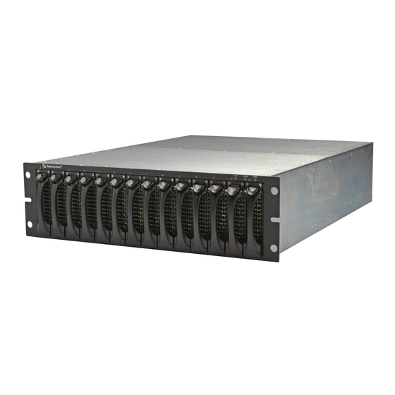
Shutting Down and Restarting an Array on page 1-6 Front and Back Panels The front and back panels of a PS Series storage array are shown below. Figure 1-1: PS Series 50E to 400E Storage Array Front Panel Figure 1-2: PS Series 50E to 400E Storage Array Back Panel... -
Page 10: Interpreting Leds
Figure 1-3: Type II Control Module Details Interpreting LEDs The following figures and tables describe PS Series 50E to 400E storage array LEDs, which can alert you to errors and conditions that require your attention. Report serious errors to your PS Series array service provider. - Page 11 PS Series 50E to 400E Hardware Maintenance Basic Array Information Table 1-1: Front Panel LED Descriptions (Continued) Array LEDs Color Description No power. Green Power. No power or normal condition. WARN One or more of the following has occurred: •...
- Page 12 PS Series 50E to 400E Hardware Maintenance Basic Array Information Figure 1-5: Back Panel LEDs Table 1-2: Back Panel LED Descriptions Control Module LEDs Color Description No power. Green Power. No power or no error condition. Array is starting up or error condition.
-
Page 13: Using An Electrostatic Wrist Strap
PS Series 50E to 400E Hardware Maintenance Basic Array Information Table 1-2: Back Panel LEDs (Continued) Fan Tray LED Color Description Outside edge of fan tray No power. Green Environmental Management Module (EMM) and fans on the fan tray are functioning. -
Page 14: Shutting Down And Restarting An Array
Basic Array Information Shutting Down and Restarting an Array PS Series 50E to 400E storage arrays include redundant, hot-swappable disks, fan trays, power supplies, and control modules (if a dual control module array). You can remove a redundant component without affecting operation if a functioning component is available. -
Page 15: Maintaining Disks
2 Maintaining Disks PS Series 50E to 400E storage arrays include up to 14 hot-swappable disks. Disk maintenance topics include: • Disk Handling Requirements on page 2-1 • Identifying Failed Disks on page 2-2 • Removing Disks on page 2-2 •... -
Page 16: Identifying Failed Disks
PS Series 50E to 400E Hardware Maintenance Maintaining Disks Identifying Failed Disks Disks in PS Series 50E to 400E storage arrays are installed in slots numbered from 0 to 13 (from left to right). A disk failure is indicated by: •... -
Page 17: Installing Disks
PS Series 50E to 400E Hardware Maintenance Maintaining Disks Figure 2-1 shows how to remove a disk from a storage array. Instructions for removing a blank carrier are similar, except you do not have to wait 10 seconds. Figure 2-1: Removing a Disk... - Page 18 PS Series 50E to 400E Hardware Maintenance Maintaining Disks Figure 2-2 shows how to install a disk in an array. Use the same instructions for installing a blank carrier. Note: Make sure the disk is oriented in the position shown below (that is, the locking latch is positioned upwards).
-
Page 19: Maintaining Control Modules
Type II control modules also include a replaceable coin cell battery to back up the NVRAM. Warning: Only install control modules of the same type in a PS Series array. A Type II control module has a blue face plate and one serial port. -
Page 20: Identifying Control Module Failures
(slot 1). Understanding Failover Behavior A PS Series storage array can have one to three active network connections. In a dual control module array, only one control module is active (actively serving I/ O) at one time. Each control module includes a battery-backed write cache for storing recently-used data. -
Page 21: Maintaining Control Module Firmware
A PS Series 50E to 400E storage array provides three types of network failure protection: • Network connection failover. If multiple network interfaces are connected to a network and one network interface fails, iSCSI initiators that were connected to the failed interface can reconnect to the group IP address and be redirected to a functioning interface. -
Page 22: Connecting Network Cables
Instead, contact your PS Series array service provider. Connecting Network Cables A PS Series storage array must have at least one and can have up to three active network connections at one time. Multiple network connections are recommended for performance and availability. - Page 23 Figure 3-1 shows how you can increase availability and performance by adding network connections to a PS Series 50E to 400E storage array with a single control module. Figure 3-1: Single Control Module Array Network Connections For example, if you connect cables as shown in Figure 3-2, and the...
- Page 24 Maintaining Control Modules Figure 3-3 shows how you can increase availability and performance by adding network connections to a PS Series 50E to 400E storage array with dual control modules. Note that you can connect all six ports for guaranteed full bandwidth under all conditions.
-
Page 25: Installing A Control Module
PS Series 50E to 400E Hardware Maintenance Maintaining Control Modules • If the cable attached to the port on the active control module (CM0) is eth2 disconnected, only will remain as network connections. This eth0 eth1 is because the port is not redundant and does not support port failover. - Page 26 PS Series 50E to 400E Hardware Maintenance Maintaining Control Modules To install a control module, attach an electrostatic wrist strap, as described in Using an Electrostatic Wrist Strap on page 1-5. Then, remove the control module from its antistatic bag and refer to the instructions in Figure 3-5.
-
Page 27: Removing A Control Module
NVRAM coin cell battery, or compact flash card. In a dual control module PS Series 50E to 400E storage array, you can remove a control module without shutting down the array, if the remaining control module has at least one connected and functioning network interface. - Page 28 If the array will permanently operate with only one control module, you must attach a blank face plate to the empty slot. You can order a blank face plate from your PS Series array service provider. Do not leave a control module slot empty.
-
Page 29: Replacing The Compact Flash Card
Maintaining Control Modules Replacing the Compact Flash Card Each control module includes a compact flash card running the PS Series storage array firmware. You must replace a compact flash card if the card fails on an otherwise functioning control module. Be sure to order a replacement card with the same firmware version as the failed card. -
Page 30: Replacing The Cache Battery
The cache battery status appears in the field. If the status is Battery status , contact your PS Series array service provider to low-voltage failed obtain a replacement battery. Control module behavior when a cache battery has low voltage (or fails) depends on whether you have a single or dual control module array and the cache mode 3–12... - Page 31 PS Series 50E to 400E Hardware Maintenance Maintaining Control Modules policy settings, as described in the PS Series Group Administration manual and summarized here: • On a member with a single control module, if the low-battery-safe policy is enabled and the charge on the cache battery is low, the cache will be flushed and will operate in write-through mode until the cache battery is recharged or replaced.
- Page 32 PS Series 50E to 400E Hardware Maintenance Maintaining Control Modules To replace a control module cache battery, follow these steps and refer to the specified sections and figures: 1. Attach an electrostatic wrist strap. See Using an Electrostatic Wrist Strap on page 1-5.
-
Page 33: Replacing The Nvram Coin Cell Battery
NVRAM Status NVRAM Battery Contact your PS Series array service provider to obtain a replacement battery. Note: It is recommended that you do not replace a coin cell battery during a power failure. This is because the NVRAM may contain useful data. - Page 34 PS Series 50E to 400E Hardware Maintenance Maintaining Control Modules module array without shutting down the array, if the remaining control module has at least one connected and functioning network interface. However, if you remove the active control module (the LED labeled ACT will be green), there will be a short interruption as failover to the secondary control module occurs.
-
Page 35: Maintaining Power Supplies
4 Maintaining Power Supplies PS Series 50E to 400E storage arrays contain either two Model 20-0002 power supplies or two Model 20-0005 power supplies. Warnings: Do not mix power supply types in an array or you risk losing data. Power cables shipped with the array should only be used with this product. -
Page 36: Removing A Power Supply
PS Series 50E to 400E Hardware Maintenance Maintaining Power Supplies To identify the model number, examine the power supply face plate. Table 4-1 shows the power supply face plates and their corresponding model numbers. Table 4-1: Power Supply Model Numbers... -
Page 37: Installing A Power Supply
PS Series 50E to 400E Hardware Maintenance Maintaining Power Supplies Figure 4-1: Removing a Power Supply Installing a Power Supply To install a power supply, refer to Figure 4-1 and follow these steps: 1. Ensure that you have the right power supply model, as described in Identifying the Power Supply Model on page 4-1. -
Page 39: Maintaining Fan Trays
5 Maintaining Fan Trays PS Series 50E to 400E storage arrays include two hot-swappable fan trays, each with two fans. Fan tray maintenance topics include the following: • Identifying Fan Tray Failures on page 5-1 • Removing a Fan Tray on page 5-1 •... -
Page 40: Installing A Fan Tray
PS Series 50E to 400E Hardware Maintenance Maintaining Fan Trays Figure 5-1 shows how to remove a fan tray from an array. Caution: The fans may still be rotating after the fan tray is removed, so handle the exposed fan tray with care. -
Page 41: A Environmental, Power, And Physical Requirements
A Environmental, Power, and Physical Requirements Table A-1 describes the environmental, power, and physical requirements for PS Series 50E to 400E storage arrays. Table A-1: Storage Array Requirements Component Requirement Weight of fully-loaded array 92 pounds or 41.82 kilograms (14 disks and two control modules) -
Page 43: B Control Module Models
PS Series Firmware Version 2.2 and later firmware versions support the Type II control module for PS Series 50E to 400E storage arrays. This control module is functionally equivalent to a Type I control module, but has a few physical differences, as described in this appendix. -
Page 44: Model Differences
Type I and Type II control module models have equivalent functionality and design, with these exceptions: • Type II can only run PS Series Firmware Version 2.2 or a higher firmware version. Type I supports all firmware versions. • Type II has a single serial port (Port 0). Type I has two serial ports (Port 0 and Port 1). - Page 45 PS Series 50E to 400E Hardware Maintenance Control Module Models Figure B-3: Serial Connection to a Type II Control Module Figure B-4: Serial Connection to a Type I Control Module B–3...
-
Page 47: Index
Index array cables (network) back panel connecting 3-12 battery, cache copper-based networks 3-15 battery, coin cell fibre optic networks control module models 1-6, B-2 cables (serial), connecting control module restriction 3-12 cache, battery control modules disks compact flash card environmental requirements firmware requirements fan trays identifying firmware... - Page 48 PS Series 50E to 400E Hardware Maintenance Index model differences power supplies port redundancy fans protecting indications of failure removing from array initialization 3-1, 3-7 restriction installing fan tray in array serial connection locating 1-4, 3-1 synchronizing 5-1, removing fan tray from array...
- Page 49 PS Series 50E to 400E Hardware Maintenance Index model restriction removing from array 1-6, B-2 serial connection, making verifying operational status shutting down an array 1-4, synchronizing control modules requirements 3-13 cache battery 3-15 coin cell battery control modules upgrading to a dual control module...
Need help?
Do you have a question about the PS Series and is the answer not in the manual?
Questions and answers