CipherLab 8500 Series Reference Manual
Hide thumbs
Also See for 8500 Series:
- Reference manual (107 pages) ,
- Operator's reference manual (103 pages) ,
- Quick manual (2 pages)
Table of Contents
Advertisement
Quick Links
Advertisement
Table of Contents

Related Manuals for CipherLab 8500 Series


Summary of Contents for CipherLab 8500 Series
- Page 1 8500 Series Mobile Computer 8500/8570 Version 2.21...
- Page 2 Due to continued product development this information may change without notice. The information and intellectual property contained herein is confidential between CIPHERLAB and the client and remains the exclusive property of CIPHERLAB CO., LTD. If you find any problems in the documentation, please report them to us in writing.
-
Page 3: For Canada
IMPORTANT NOTICES FOR USA This equipment has been tested and found to comply with the limits for a Class B digital device, pursuant to Part 15 of the FCC Rules. These limits are designed to provide reasonable protection against harmful interference in a residential installation. This equipment generates, uses and can radiate radio frequency energy and, if not installed and used in accordance with the instructions, may cause harmful interference to radio communications. -
Page 4: For Product With Laser
DISPOSE OF USED BATTERIES ACCORDING TO THE INSTRUCTIONS. The use of any batteries or charging devices, which are not originally sold or manufactured by CipherLab, will void your warranty and may cause damage to human body or the product itself. -
Page 5: Release Notes
RELEASE NOTES Version Date Notes Modified: 3.7 Bluetooth Menu — Not maintain Bluetooth PAN 2.21 Mar. 09, 2011 (=BNEP) from 2011 Modified: Specifications — add power adaptor spec. New: Appendix III Key Reference Tables 2.20 Oct. 28, 2010 Modified: Remove support of 8580/8590 Modified: 1.6.1 Symbologies Supported —... - Page 6 1.03 May 23, 2006 Company name changed to CIPHERLAB CO., LTD. since April 2006 New: Safety Precaution Modified: Care & Maintenance Modified: 1.2.3 Dimensions & Specifications Modified: 1.3.4 Keypad – Screen Icons Modified: 1.3.5 LCD – Screen & Backlight Settings Modified: 1.3.12 Application Software to include AG and CipherNet...
-
Page 7: Table Of Contents
CONTENTS IMPORTANT NOTICES ........................- 3 - For USA ............................- 3 - For Canada ............................ - 3 - For Hand-held Product with RF Functions ................... - 3 - For Product with Laser ........................- 4 - Safety Precautions ........................- 4 - Care &... - Page 8 8500 Series Mobile Computer Reference Manual 1.6.1 Symbologies Supported....................26 1.6.2 RFID Tags Supported ....................... 28 1.7 Charging & Communications ....................29 1.7.1 Cradle Options........................29 1.7.2 Understanding the LED Indicators ..................33 1.7.3 4-Slot Battery Charger .....................34 LEARNING SOFTWARE ARCHITECTURE..................... 35 2.1 Application Module........................37 2.1.1 FORGE Application Generator (AG) .................
- Page 9 8500 Series Mobile Computer Reference Manual 3.7.4 Echo Tests ........................57 3.7.5 Pairing Test........................60 3.7.6 Freq. Dev. List........................61 3.7.7 Network Setting........................62 3.8 Serial PPP Menu ........................63 3.8.1 Information ........................63 3.8.2 Connection Set ......................... 64 3.8.3 Echo Test .......................... 65 3.9 IR Network Menu (Ethernet via IR) ..................66 3.9.1 Information ........................66...
- Page 10 8500 Series Mobile Computer Reference Manual Cannot scan barcodes ........................94 Low battery condition.........................94 Barcode or RFID reader problem ....................94 Cannot decode data after scanning....................94 Unreadable barcode ........................94 Un-programmed to read ......................94 Dirty scan window ........................94 Out of scanning range........................94 Cannot transmit/receive data ......................95...
-
Page 11: Introduction
802.11b/g, enabling all the time, anywhere applications and seamless real time sharing of performance. The 8500 Series Mobile Computer is bundled with powerful and rich features to ensure success in timely processing of information, even in rigorous industrial environments, and... -
Page 12: Getting Familiarized With 8500
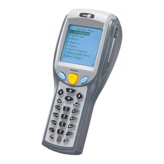
8500 Series Mobile Computer Reference Manual GETTING FAMILIARIZED WITH 8500 Figure 1: Overview Description Description LCD touch screen LED for Good Read and battery charging Keypad, 24 or 44 keys Communication/charging port Stylus Scanning window Hand strap (to be screwed) -
Page 13: Features
INSIDE THE PACKAGE The following items are included in the package. Save the box and packaging material for future use in case you need to store or ship the mobile computer. 8500 Series mobile computer Rechargeable Li-ion battery pack Stylus... -
Page 14: Accessories
8500 Series Mobile Computer Reference Manual ACCESSORIES Rich choices of optional accessories are available for you to enhance the total performance of the mobile computer. Pistol Grip (detachable) Belt Holster Protective Cover Spare rechargeable Li-ion battery 4-slot Battery Charger Charging & Communication Cradle... -
Page 15: Getting Started
Introduction GETTING STARTED INSTALLING HAND STRAP The hand strap is ideal for one-handed operation, which requires safe and convenient hold of the mobile computer. Warning: Always make sure the hand strap is well hooked and screwed to the back of the mobile computer before use. When the hand strap is desired, install it to the mobile computer by following these steps: 1) Place the mobile computer face down on a flat and clean surface. -
Page 16: Installing Pistol Grip
8500 Series Mobile Computer Reference Manual INSTALLING PISTOL GRIP This contoured pistol grip enables intuitive trigger-and-scan operation, which is very helpful in scan intensive applications. When the pistol grip is desired, install it to the mobile computer by following these steps: 1) Place the mobile computer face down on a flat and clean surface. -
Page 17: Inserting Battery
Introduction INSERTING BATTERY For shipping and storage purposes, save the mobile computer and the main battery in separate packages. This will keep both batteries in good condition for future use. Note: Any improper handling may reduce the battery life. 1) Hold the mobile computer still as shown below. 2) Slide the battery pack into the battery compartment at a proper angle (30°~45°) so that the metal contacts of the battery are met with the charging contacts inside the compartment. -
Page 18: Initial Charging
8500 Series Mobile Computer Reference Manual INITIAL CHARGING The main and backup batteries may not be charged to full for shipment. When you first receive the package, you will need to charge batteries to full before using the mobile computer. You may use a cradle or charger to charge the Mobile Computer or spare batteries. -
Page 19: Using 8500 Mobile Computer
Chapter 1 USING 8500 MOBILE COMPUTER This chapter explains the features and usage of the 8500 Series Mobile Computer. The 8500 family includes: 8500 Bluetooth Class 2 8570 Bluetooth Class 2 + 802.11b/g IN THIS CHAPTER 1.1 Battery............... 9 1.2 Memory..............11 1.3 Keypad.............. -
Page 20: Backup Battery
8500 Series Mobile Computer Reference Manual 1.1.2 BACKUP BATTERY The backup battery on the main board takes charge when the main battery is removed or drained out. When fully charged, the 3.0 V/7 mAh rechargeable Lithium button cell helps retain data in SRAM and maintain the running of the real-time clock and calendar for at least one week without the main battery. -
Page 21: Memory
Chapter 1 Using 8500 Mobile Computer 1.2 MEMORY The collected data can be sent back to a host computer immediately over wireless networks, or stored in memory (SRAM) and upload later. The mobile computer is equipped with a calendar chip for accurate time/date logging. When the main battery is removed or drained, the backup battery on the main board is to retain the contents of SRAM and maintain the running of real-time clock and calendar for at least one week, on condition that the backup battery has already been fully charged. -
Page 22: Keypad
8500 Series Mobile Computer Reference Manual 1.3 KEYPAD The mobile computer can be equipped with a keypad of 24 keys or 44 keys for system setup, user entry and so on. The keypad comes with programmable LED backlight, like the screen. Refer to section 1.4 LCD... - Page 23 Chapter 1 Using 8500 Mobile Computer This alphanumeric keypad is set to numeric mode by default. The [ALPHA] key serves as a toggle among numeric, alpha (lower-case alphabetic), and ALPHA (upper-case alphabetic) input modes. Note: It is not necessary to hold down the [ALPHA] key. The alpha icon will appear on the lower-left corner of the screen in a sequence as shown below.
- Page 24 8500 Series Mobile Computer Reference Manual Below briefly describes the functions of common keys on the mobile computer. SCAN This yellow key is used to trigger the scan engine so that it can read a barcode when the reader function is enabled.
- Page 25 Chapter 1 Using 8500 Mobile Computer FN (Function) This key is a modifier key that requires pressing a second key ([0] ~ [9]) to get the value of key combination. Icon Description By default, the function toggle is set to Auto Resume mode, and its behavior is as described below: This icon appears when you press the function key, indicating it is set to the function mode.
-
Page 26: 44-Key Layout
8500 Series Mobile Computer Reference Manual 1.3.2 44-KEY LAYOUT The layout of the 44-key keypad includes numeric, alphabetic, navigation and function keys, as well as assorted characters and modifier keys. Refer to Appendix III — Key Reference Tables for color-coded keys. - Page 27 Chapter 1 Using 8500 Mobile Computer Below briefly describes the functions of common keys on the mobile computer. SCAN This yellow key is used to trigger the scan engine so that it can read a barcode when the reader function is enabled. ENTER The two keys on each side of the SCAN key are user-friendly and convenient for either right-handed or left-handed operator.
- Page 28 8500 Series Mobile Computer Reference Manual Shift Key The alphabetic keypad is set to upper-case alphabetic mode by default. The [Shift] key serves as a toggle between lower-case and upper-case alphabetic input modes. It takes turns to show alphabets or symbols when you keep pressing the same key, one to two times (the time interval between each press must not exceed one second).
-
Page 29: 44-Te Key Layout
Chapter 1 Using 8500 Mobile Computer 1.3.3 44-TE KEY LAYOUT The layout of the 44-TE key keypad includes numeric, alphabetic, navigation and function keys, as well as modifier keys. Refer to Appendix III — Key Reference Tables for color-coded keys. Figure 7: 44-TE key Layout... - Page 30 8500 Series Mobile Computer Reference Manual This alphanumeric keypad is set to numeric mode by default. The [Alpha] key serves as a toggle among numeric, alpha (lower-case alphabetic), and ALPHA (upper-case alphabetic) input modes. Note: It is not necessary to hold down the [Alpha] key.
- Page 31 Chapter 1 Using 8500 Mobile Computer Below briefly describes the functions of common keys on the mobile computer. SCAN This yellow key is used to trigger the scan engine so that it can read a barcode when the reader function is enabled. ENTER The two keys on each side of the SCAN key are user-friendly and convenient for either right-handed or left-handed operator.
- Page 32 8500 Series Mobile Computer Reference Manual Alpha Key This key is a modifier key that requires pressing a second key to get the red-coded letter (A~Z) printed on the upper-left corner of the second key. Icon Description This icon appears when you press the [Alpha] key once, indicating it is set to alphabetic mode for typing upper-case alphabetic letters.
-
Page 33: Lcd
Chapter 1 Using 8500 Mobile Computer 1.4 LCD The mobile computer comes with a 3” FSTN graphic LCD, 160 by 160 pixels resolutions, which can be programmed to display text or graphics, such as specific font and company logo, to meet varying application needs. Options Font Size (pixels) Characters by lines... -
Page 34: Calibrating The Screen
8500 Series Mobile Computer Reference Manual 1.4.2 CALIBRATING THE SCREEN This LCD is also a touch screen, which enables the use of a stylus for handwriting. It also features signature capture that can save signature as confirmation of receipt when delivering goods to door. -
Page 35: Notifications
Chapter 1 Using 8500 Mobile Computer 1.5 NOTIFICATIONS 1.5.1 STATUS LED The dual-color LED above the [SCAN] trigger is used to provide information on the charging status and can be programmed to provide information that helps diagnosing. For example, if you are using AG Runtime, you will be informed of the scanning result immediately. -
Page 36: Data Capture
8500 Series Mobile Computer Reference Manual 1.6 DATA CAPTURE Options of different reader combination are allowed, such as 1D+RFID and 2D+RFID. For each combination, both readers can be initialized and ready for scanning at the same time (dual mode operation). For example, if you press the [SCAN] trigger while running the preloaded AG runtime on the mobile computer, it will read a barcode in position or an RFID tag in proximity depending on which one comes first. - Page 37 Chapter 1 Using 8500 Mobile Computer Disabled Enabled Enabled Plessey Disabled Postal Codes Enabled Telepen Disabled Code 128 Code 128 Enabled Enabled Enabled GS1-128 (EAN-128) Enabled Enabled Enabled ISBT 128 Enabled Enabled Enabled Code 2 of 5 Industrial 25 (Discrete 25) Enabled Enabled Enabled...
-
Page 38: Rfid Tags Supported
8500 Series Mobile Computer Reference Manual Data Matrix Enabled Maxicode Enabled QR Code Enabled 1.6.2 RFID TAGS SUPPORTED The RFID reader supports read/write operations depending on the tags. The supported labels include ISO 15693, Icode®, ISO 14443A, and ISO 14443B. Currently, the performance of some tags has been confirmed, and the results are listed below for your reference. -
Page 39: Charging & Communications
Chapter 1 Using 8500 Mobile Computer 1.7 CHARGING & COMMUNICATIONS You can use a cradle or charger to charge the mobile computer and/or its battery. 1.7.1 CRADLE OPTIONS A variety of cradles are available to meet different requirements. The cradle is designed for charging and communications at the same time. - Page 40 8500 Series Mobile Computer Reference Manual Charging & Communication Cradle Description Description LED Indicators (from left to right): Cable Connector (RS-232) Charging Receive Data Transmit Data Power Refer to 1.7.2 Understanding the LED Indicators. Power Jack...
- Page 41 Chapter 1 Using 8500 Mobile Computer Modem Cradle Delivering flexibility in making a connection, the Modem Cradle integrates the modem functionality (56 kbps) into the cradle. You may choose to use the modem or RS-232 port by sliding the DIP switch. Modem Connection To use the modem functionality, slide the DIP switch to right: When the power cable is properly connected, the LED light of POWER on the front panel will...
- Page 42 8500 Series Mobile Computer Reference Manual Ethernet Cradle Refer to the Ethernet Cradle manual for more information. Auto-detect Connection Slide the DIP switch to left: The RS-232 connection will override Ethernet connection when both are present. However, you can use cradle commands to switch in between the two.
-
Page 43: Understanding The Led Indicators
Chapter 1 Using 8500 Mobile Computer 1.7.2 UNDERSTANDING THE LED INDICATORS For charging status of the loaded battery in the mobile computer, view the device screen. Figure 9: Cradle LEDs Indicator Status Description Battery not ready (Spare battery charging) Red, solid Charging Green, solid Charging done... -
Page 44: 4-Slot Battery Charger
8500 Series Mobile Computer Reference Manual 1.7.3 4-SLOT BATTERY CHARGER Below is the 4-Slot Battery Charger. 1) The Battery Charger can be mounted on table or wall. Drill two holes (centers spaced 160 millimeters apart), secure the two supplied screws, and mount the Battery Charger by sliding over screws. -
Page 45: Learning Software Architecture
Chapter 2 LEARNING SOFTWARE ARCHITECTURE This chapter mainly describes the software inside the mobile computer. It consists of three modules — Kernel, System, and Application; each has a function menu. When a menu is displayed, you may select an item by either of the following ways: Press the arrow keys [Up] and [Down] to move the highlight bar. - Page 46 8500 Series Mobile Computer Reference Manual On each screen, the bottom line displays status icons, such as: The 4-bar battery icon indicates the current power status. The status icon of input or function mode is controlled by the modifier key.
-
Page 47: Application Module
Chapter 2 Learning Software Architecture 2.1 APPLICATION MODULE The mobile computer ships with software package on the CD-ROM. It includes FORGE Application Generator (batch and WLAN versions), MIRROR Emulator (VT and 5250 versions), download utilities, etc. 2.1.1 FORGE APPLICATION GENERATOR (AG) For easy development of applications, the mobile computer is preloaded with AG runtime. -
Page 48: Mirror Emulator (Ciphernet)
Companion Tool on PC End VT100/220 85xx-VT.SHX CipherNet-VT.exe IBM 5250 85xx-5250.SHX CipherNet-5250.exe 2.1.3 USER PROGRAM You may need to develop your own application program. For developing custom applications, CipherLab provides BASIC and C compilers through licensing. For detailed information, please contact your sales representative. -
Page 49: System Configuration & Core
For managing system configurations and multiple programs, each mobile computer comes with the System Menu, Program Manager, and Kernel. Refer to the following chapters on how to configure the 8500 Series Mobile Computer, regarding system configurations and program download. 2.2.1 SYSTEM MENU System Menu is bundled with BASIC Runtime or user programs that are written in “C”. - Page 50 8500 Series Mobile Computer Reference Manual...
-
Page 51: System Menu
Chapter 3 SYSTEM MENU System Menu is generated by a powerful utility, which offers an interface for engineers (programmers system integrator) view system information, change configuration parameters, download programs and run diagnostics. This menu is designed for engineering tests and maintenance ONLY. For this reason, it provides password protection to prevent unauthorized users from accidentally changing system settings. -
Page 52: Information
8500 Series Mobile Computer Reference Manual IN THIS CHAPTER 3.1 Information............... 42 3.2 Settings ..............44 3.3 Tests ............... 47 3.4 Memory..............49 3.5 Power ..............50 3.6 Load Program............51 3.7 Bluetooth Menu ............53 3.8 Serial PPP Menu............63 3.9 IR Network Menu ............ -
Page 53: Understanding Device Code
Chapter 3 System Menu 3.1.1 UNDERSTANDING DEVICE CODE Device Code Modular Component Types 1st digit Reader module 0= none 1= CCD scan engine 2= Laser scan engine 3= 2D scan engine 4= Long Range Laser scan engine 5= Extra Long Range Laser scan engine 2nd digit Wireless module 4= Bluetooth + 802.11b/g... -
Page 54: Settings
8500 Series Mobile Computer Reference Manual 3.2 SETTINGS You can change the default settings here. System Settings Default Values Clock Current time Backlight Period 20 seconds, Level 2 Auto Off 10 minutes Power On Options Program Resume Key Click Tone 2... -
Page 55: Power On Options
Chapter 3 System Menu 3.2.4 POWER ON OPTIONS Set the startup screen once the mobile computer is turned on. Press the arrow keys [Up] and [Down] to select “[0] Program Resume” or “[1] Program Restart”, and then press [ENTER]. Program Resume: When selected, the mobile computer will start from the last session of program before it is turned off. -
Page 56: Reset Reader
8500 Series Mobile Computer Reference Manual 3.2.10 RESET READER Reset reader settings to the default values when one of the following scan engines is installed for use: 2D scan engine Long Range Laser scan engine Extra Long Range Laser scan engine 3.2.11 LCD HEATER... -
Page 57: Tests
Chapter 3 System Menu 3.3 TESTS Here provides functional tests for key parts. 3.3.1 READER Test the reading performance of the scanner. The supported symbologies depend on the scan engine you use. Refer to 1.6 Data Capture for symbologies that are enabled by default. -
Page 58: Touch Screen
8500 Series Mobile Computer Reference Manual 3.3.6 TOUCH SCREEN Test signature capture by using the stylus for handwriting. To stop and exit the test, press [ESC] or tap [OK] on the screen. 3.3.7 VIBRATOR Test the vibrator. To stop and exit the test, press [ESC]. -
Page 59: Memory
Chapter 3 System Menu 3.4 MEMORY Here provides information and initialization function of the memory. 3.4.1 SIZE INFORMATION Base RAM — onboard SRAM for data memory Memory Card — optional data memory Flash — program memory 3.4.2 INITIALIZE Initialize the data memory, Base RAM or Memory Card. Warning! The contents of the data memory (SRAM) will be wiped out after memory initialization. -
Page 60: Power
8500 Series Mobile Computer Reference Manual 3.5 POWER Here shows current voltage consumption. Main (battery) It shows dynamic status of the battery pack, which is used as the main power source. Backup (battery) It shows dynamic status of the button cell, which is used to retain data in SRAM. -
Page 61: Load Program
Chapter 3 System Menu 3.6 LOAD PROGRAM Here you can access the Load Program service provided by the kernel. Because the kernel will take over the job, you will not be able to return to System Menu by pressing [ESC]. After downloading, restart the mobile computer to activate the new program. Refer to Appendix I Download Utility. - Page 62 IrDA Point to the target IrDA device. Bluetooth Approach the target Bluetooth enabled device. Baud Rate Options Supported by CipherLab software, including download utilities 115200 (bps) 76800 (bps) 57600 (bps) 38400 (bps) 19200 (bps) 9600 (bps) 4800 (bps)
-
Page 63: Bluetooth Menu
Bluetooth enabled devices. You must configure these parameters correctly. Note: Due to the fact that the production of 3560 (Bluetooth Access Point) has been discontinued, CipherLab will cease to maintain the Bluetooth PAN (=BNEP) functionality on the mobile computer since the year of 2011. -
Page 64: Information
8500 Series Mobile Computer Reference Manual 3.7.1 INFORMATION Information of network configuration can be viewed here. Bluetooth Menu | 1. Information C library version MAC address of the Bluetooth module A name given to the mobile computer for identification By default, it is made up of model number and the serial number. (Identical to 2. -
Page 65: Connect Setting
Chapter 3 System Menu 3.7.2 CONNECT SETTING Set the connection parameters if necessary. Local Name Enter a name for identifying the mobile computer. By default, it is made up of model number and the serial number. Remote Name Enter a name for making a specific connection. The remote name must be one of those in the Freq. -
Page 66: Security
8500 Series Mobile Computer Reference Manual 3.7.3 SECURITY Set or modify security parameters. Authentication Options — Enable or Disable PIN Code Define the encryption key values. Up to 16 characters, using ASCII code. Note: When authentication is enabled without providing a pre-set PIN code, the mobile... -
Page 67: Echo Tests
Chapter 3 System Menu 3.7.4 ECHO TESTS These echo tests are used for verifying connectivity to make sure the mobile computer is within coverage. Press [ESC] to stop and exit the test. In PAN mode, the echo test helps measure the coverage of the range, estimate the number of APs and mobile computers needed, and determine the topology of deploying APs. - Page 68 8500 Series Mobile Computer Reference Manual SPP Master Set the mobile computer as a master device. 1. Pairing with your computer (slave) must be completed first. 2. Run the utility “EchoTest.exe” on your computer. Associated settings include - Select “RS-232” for interface.
- Page 69 Chapter 3 System Menu DUN GPRS The mobile computer will try to connect to a mobile phone with GPRS functionality. 1. Pairing with your mobile phone must be completed first. Select “DialUp Network” for Target Machine options. 2. Run the utility “EchoTest.exe” on your computer. Associated settings include - Select “TCP/IP –...
-
Page 70: Pairing Test
8500 Series Mobile Computer Reference Manual 3.7.5 PAIRING TEST The pairing procedure is for the creation and exchange of a link key between two Bluetooth-enabled devices. The devices use the link key for future authentication when exchanging information. 1) The mobile computer will start with making an inquiry so that the system can generate a list of device(s) that has been discovered nearby. -
Page 71: Freq. Dev. List
Chapter 3 System Menu 3.7.6 FREQ. DEV. LIST The Frequent Device List is used to store a list of target device(s) that the mobile computer has been connected to lately. After each successful pairing, the system will update the list. Note: To unpair any device, simply delete the device from this list. -
Page 72: Network Setting
8500 Series Mobile Computer Reference Manual 3.7.7 NETWORK SETTING Set parameters for IP networking. DHCP Options — Enable or Disable Subnet Mask Enter a new Mask IP, if necessary. Local IP Address Enter a new address for the mobile computer, if necessary. -
Page 73: Serial Ppp Menu
Chapter 3 System Menu 3.8 SERIAL PPP MENU This submenu is for establishing a PPP connection via the Modem Cradle. You must configure these parameters correctly. Point-to-Point Protocol (PPP) is a method of connecting the mobile computer to the Internet over serial links. It sends TCP/IP packets to a server that connects to the Internet. -
Page 74: Connection Set
8500 Series Mobile Computer Reference Manual 3.8.2 CONNECTION SET DialUp Number Enter the number provided by your ISP. Login Name Enter the login name provided by your ISP. Login Password Enter the login password provided by your ISP. Baud Rate Select a desired baud rate. -
Page 75: Echo Test
Chapter 3 System Menu 3.8.3 ECHO TEST This echo test is used for verifying connectivity via Point-to-Point Protocol. For the Modem Cradle, its physical connectivity can be verified in System Menu | Tests | Echo Test | IR or MODEM. Note: Enter the IP address of a server with which a PPP connection is desired. -
Page 76: Ir Network Menu (Ethernet Via Ir)
8500 Series Mobile Computer Reference Manual 3.9 IR NETWORK MENU (ETHERNET VIA IR) This submenu is for establishing an Ethernet connection via IR networking. You must configure these parameters correctly. Note: The Ethernet Cradle is required for establishing Ethernet connection via IR. -
Page 77: Network Setting
Chapter 3 System Menu 3.9.2 NETWORK SETTING Set parameters for IP networking. DHCP Options - Enable or Disable Subnet Mask Enter a new Mask IP, if necessary. Local IP Address Enter a new address for the mobile computer, if necessary. Default Gateway Enter a new address for the default Gateway, if necessary. -
Page 78: Echo Tests
8500 Series Mobile Computer Reference Manual 3.9.3 ECHO TESTS The Ethernet Cradle supports three working modes: Data Mode Modem Mode Transparent Mode These echo tests are used for verifying connectivity via the Ethernet Cradle. For details, refer to the Ethernet Cradle manual. -
Page 79: Wi-Fi Menu
Chapter 3 System Menu 3.10 WI-FI MENU This submenu is for 802.11b/g wireless networking. You must configure these parameters correctly. Note: The menu is available only when the Wi-Fi module is present. Wi-Fi Settings Default Value Ad-hoc Infrastructure Network Setting Items Need to Be Checked DHCP Enabled... -
Page 80: Information
8500 Series Mobile Computer Reference Manual 3.10.1 INFORMATION Information of network configuration can be viewed here. Wi-Fi Menu | 1. Information Firmware version of the Wi-Fi module MAC address of the Wi-Fi module A name given to the mobile computer for identification. -
Page 81: Network Setting
Chapter 3 System Menu 3.10.2 NETWORK SETTING Set parameters for IP networking. DHCP Options — Enable or Disable Subnet Mask Enter a new Mask IP, if necessary. Local IP Address Enter a new address for the mobile computer, if necessary. Default Gateway Enter a new address for the default Gateway, if necessary. -
Page 82: Wlan Setting
8500 Series Mobile Computer Reference Manual 3.10.3 WLAN SETTING Wireless networking can operate in two modes – (1) Ad-hoc mode: peer-to-peer, and (2) Infrastructure mode: point to multi-point through access points. Set the following parameters. Local Name Enter a name for identifying the mobile computer. - Page 83 Chapter 3 System Menu Fixed BSSID This refers to the use of a specific AP’s MAC address as the fixed Basic Service Set Identifier. The mobile computer can ONLY communicate with this one and only access point.
-
Page 84: Security
8500 Series Mobile Computer Reference Manual 3.10.4 SECURITY Set or modify security parameters. WEP: Wired Equivalent Privacy EAP: Extensible Authentication Protocol WPA: Wi-Fi Protected Access Authentication Default authentication type [1] Open System This requires implementing WEP key. [0] Share Key... -
Page 85: Echo Tests
Chapter 3 System Menu 3.10.5 ECHO TESTS This function is used to measure the coverage of the range, estimate the number of APs and mobile computers needed, and determine the topology of deploying APs. Client Mode Set the mobile computer as a client. Enter the IP address of a server with which a connection is desired. - Page 86 8500 Series Mobile Computer Reference Manual The changing icon indicates 8500 is processing a pre-share key. Wait for a few seconds. The antenna icon will become ready and flashes to indicate 8500 is connecting to an access point under the same SSID.
- Page 87 Chapter 3 System Menu Once the connection of echo test is established, the details will be displayed as illustrated below. Link Quality (“Q”) will be the most important element while the others are for your reference. Q (Link Quality) T (Transmit Speed) S (Signal Level) N (Noise Level) 0 ~ 10...
- Page 88 8500 Series Mobile Computer Reference Manual...
-
Page 89: Program Manager & Kernel
Chapter 4 PROGRAM MANAGER & KERNEL This chapter explains Program Manager and Kernel that manage multiple programs and firmware upgrade. IN THIS CHAPTER 4.1 Program Manager ............79 4.2 Kernel ..............84 4.1 PROGRAM MANAGER The mobile computer supports multiple applications and languages. In the menu of Program Manager, it allows storing up to seven programs and has one activated for the current use. -
Page 90: Download
8500 Series Mobile Computer Reference Manual 4.1.1 DOWNLOAD Here provides a full list of programs that are currently stored on the mobile computer with size information. Multiple application programs can be downloaded through a variety of interfaces. Upon completion of downloading, you are allowed to input a name for the program. - Page 91 Chapter 4 Program Manager & Kernel SPARE MEMORY SECTORS (1 ~ 6) Additional program files can be directly downloaded to these sectors. Download a program file to an empty sector: 1. Press the arrow keys [Up] and [Down] to select an empty sector, and then press [ENTER]. 2.
-
Page 92: Activate
8500 Series Mobile Computer Reference Manual 4.1.2 ACTIVATE The list shows the entire spare programs stored on the mobile computer. From the list, you can select from the memory sector (1 to 6). The selected program will be copied to the active memory sector and replace the current one. -
Page 93: Upload
Chapter 4 Program Manager & Kernel 4.1.3 UPLOAD You may duplicate one or all of the programs from the mobile computer to a host computer or another mobile computer. This can be used to clone software on mobile computers. Note: To clone all of the programs, the target mobile computer cannot have any other program downloaded except the active one;... -
Page 94: Kernel
8500 Series Mobile Computer Reference Manual 4.2 KERNEL The kernel resides in the innermost core of the system. It has the highest security and is always protected by the system. When the application program is corrupted and System Menu fails at the same time, Kernel Menu provides an access to fix the system. -
Page 95: Kernel Information
Chapter 4 Program Manager & Kernel 4.2.1 KERNEL INFORMATION Here provides important system information to help diagnose the system. Kernel Menu | 1. Information Hardware version Serial number of the mobile computer Manufacturing date Kernel version 5-digit code for optional hardware configurations Refer to Understanding Device Code. -
Page 96: Load Program
8500 Series Mobile Computer Reference Manual 4.2.2 LOAD PROGRAM You can download one program file to the active memory sector, as well as one font file to the memory address assigned by the system. After downloading, restart the mobile computer to activate the new program. Refer to Appendix I Download Utility. - Page 97 IrDA Point to the target IrDA device. Bluetooth Approach the target Bluetooth enabled device. Baud Rate Options Supported by CipherLab software, including download utilities 115200 (bps) 76800 (bps) 57600 (bps) 38400 (bps) 19200 (bps) 9600 (bps) 4800 (bps)
-
Page 98: Kernel Update
Do not turn off the mobile computer while downloading a kernel update or re-starting the mobile computer. Otherwise, it will crash the kernel forever. There is no way to recover it! Note: CipherLab software, including download utilities, supports the following baud rate options: 115200/57600/38400/19200/9600 bps. 4.2.4 TEST & CALIBRATE These tools are provided for manufacturing use. -
Page 99: Specifications
SPECIFICATIONS Model Designation 8500 8570 Wireless IR/IrDA √ √ Communications Bluetooth Class 2 √ √ 802.11b/g √ Readers Barcode Reader CCD (linear imager) Standard Laser Long Range Laser Extra Long Range Laser 2D Imager RFID Reader Frequency 13.56 MHz Electrical Main Battery Rechargeable Li-ion battery –... - Page 100 8500 Series Mobile Computer Reference Manual Dimensions 230 mm (L) 91 mm (W) 65 mm (H) Weight Approx. 600 g (Laser, battery included) Environmental Temperature Operating: -20 °C to 60 °C (8500) Characteristics -10 °C to 60 °C (8570) Storage: -30 °C to 70 °C...
-
Page 101: Download Utility
Appendix I DOWNLOAD UTILITY For easy development of applications, the mobile computer ships with FORGE Application Generator programs, batch and WLAN versions, as well as a download utility. FILE TYPES Depending on the file type, you may download a program or font file via System Menu, Program Manager or Kernel Menu. -
Page 102: Progload.exe
8500 Series Mobile Computer Reference Manual PROGLOAD.EXE The utility “ProgLoad.exe” is provided for you to download a program (*.SHX or *.SYN) to the mobile computer. Run the program on your computer. The following dialog box pops up. Click to select Comm type, COM port, and Baud rate. -
Page 103: Troubleshooting
Try to re-charge the battery and monitor the charging status. Warning! Only use batteries or charging device manufactured by CipherLab. The use of wrong battery or charging device could result in damage to human body or the product itself, and will void your warranty. -
Page 104: Vibrator Seems Not Working
8500 Series Mobile Computer Reference Manual VIBRATOR SEEMS NOT WORKING Perform the vibrator test. (See 3.3.7 Vibrator.) If the problem persists, reload the battery pack and perform the test again. MOBILE COMPUTER SEEMS NOT WORKING Upload all data to the host and perform the memory test. (See 3.3.5... - Page 105 Appendix II Troubleshooting CANNOT TRANSMIT/RECEIVE DATA VIA IR PORT Make sure the mobile computer's infrared port is pointed directly to the infrared port of another IR device. Make sure the distance between the mobile computer and a target device is within proper range, and no obstacles in between.
- Page 106 8500 Series Mobile Computer Reference Manual VIA MODEM CRADLE Check if the modem connection is correct and secured. Make sure the modem parameters are configured properly. Try to establish connection again. Make sure the mobile computer is well seated inside the cradle. DO NOT remove the mobile computer or disconnect the cradle before communications are done.
- Page 107 Appendix III KEY REFERENCE TABLES 24-KEY KEYPAD SYSTEM DEFAULTS [ALPHA] [ALPHA] [FN] [FN] key pressed key pressed pressed pressed once twice once twice Space Space PQRS pqrs WXYZ wxyz %#;, %#;,...
- Page 108 8500 Series Mobile Computer Reference Manual 44-KEY KEYPAD SYSTEM DEFAULTS [Shift] [Shift] pressed pressed pressed once twice once / held down...
- Page 109 Appendix III Key Reference Tables 44-TE KEY KEYPAD SYSTEM DEFAULTS [Alpha] key [Alpha] key Blue pressed pressed pressed once twice once & < >...
- Page 110 8500 Series Mobile Computer Reference Manual [Alpha] key [Alpha] key Blue pressed pressed pressed once twice once null null null...
Need help?
Do you have a question about the 8500 Series and is the answer not in the manual?
Questions and answers