Fireye NX6100 Manual
Type2 oxygen probe system for nexus
Hide thumbs
Also See for NX6100:
- Commissioning manual (306 pages) ,
- Manual (222 pages) ,
- Operator's manual (62 pages)

Subscribe to Our Youtube Channel
Related Manuals for Fireye NX6100


Summary of Contents for Fireye NX6100
- Page 1 NXPK2244 July 24, 2019 Type2 Oxygen probe system for Nexus NX6100 and PPC6000 Supplement to NEX6101 & PPC6001 1 of 27...
-
Page 2: Installation And Wiring
Introduction This supplement is intended to be additional information to that contained in the standard Nexus Installation and Commissioning Bulletin. This document details the wiring configurations for the Type2 Oxygen probe system. The Type2 component system will replace the original system by March 31st, 2017. - Page 3 3 of 27...
- Page 4 4 of 27...
- Page 5 Wiring Read this document in conjunction with the product bulletin NEX-6101 & PPC6000 Disconnect the power supply before beginning installation to prevent electrical shock, equipment and/or control damage. More CAUTION than one power supply disconnect may be involved. Wiring must comply with all applicable codes, ordinances and ...
- Page 6 Secure all cables carried in conduit at both ends using a suitable anchorage method in the cabinet. Connect all signal cable ‘braid’ screens to earth using the screen termination clamps provided on the controller. Connect all cable screens to earth at the controller only, unless stated otherwise in this section.
- Page 7 1.3.2 Terminal connections and layout. Terminal No. Module Function Voltage Rating O2 Trim Interface CAN 24Vac Supply 24 – 32Vac O2 Trim Interface CAN 24Vac Supply 24 – 32Vac O2 Trim Interface CAN + (High) 0-5V O2 Trim Interface CAN – (Low) 0-5V O2 Trim Interface GND (4-20mA Input 0V)
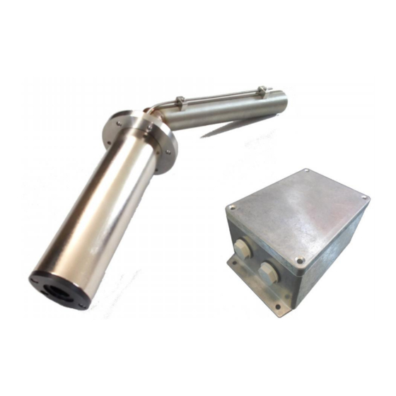
- Page 8 Internal view of NXO2TRIM. Cable entries on this face Probe connection terminals. PH1 to PH8 CAN and 4-20mA connection terminals PG1 to PG8 Ring terminal point for screen termination. Do not Connect 120Vac NXO2TRIM is 24Vac supplied 8 of 27...
- Page 9 View of NXPK224455-56-57 oxygen probe terminals. Calibration port. Removable terminal block NOTE: There is no screen termination point. The screen in the 6-way cable must be cut short to the PVC outer cover. 9 of 27...
- Page 10 Commissioning and Calibration process. There are no changes to the Commissioning and Calibration process when using the Type2 Oxygen probe system. A card with Calibration data will be provided with every new probe in a similar way to that for NXO2PK probe. Refer to bulletin NEX-6101 or PPC6001 for all processes.
- Page 11 Using adjust ratio mode to modify and existing oxygen profile manually, follow steps 1 -12 listed below. CAUTION When using the adjust ratio mode, it is not possible for the unit to check drive positions at all times. It is the responsibility of the engineer to check that motors and valves are responding correctly.
- Page 12 When using another manufacturer’s O2 probe with a 4-20mA signal for the O2 value, enter the O2 value for 20.0mA in this option parameter. Example 21% O2 = 210. NOTE: If the value of 30.1 and 30.2 are both below 300, the NX6100 will utilize the analog input on the NXO2TRIM terminals PG6(+)PG5(-)to determine the O2 signal.
- Page 13 Closed loop trim. The oxygen value is used to provide both a display of the measured oxygen level and a feedback signal for closed loop trim control function of the NX6100 series control. Option 30.6 - Oxygen probe calibrate enable (0 – 2) LV3 This option parameter is only available if option 30.0 is non-zero.
- Page 14 Option 30.7 - Boiler transport delay (5 – 60 seconds) LV3 Boiler transport delay is the time taken for 'gas' to travel from the burner to the oxygen probe. This delay varies with burner fire rate. In order for the oxygen trim control loop to be stable, this parameter must be set accurately to the transport delay of the boiler when at low fire.
- Page 15 The unit moves the air drives up to the point above the current set point, leaving the fuel drive in the same position. The display will show ‘Flow calc An + 1’. When the new oxygen reading settles, the unit calculates and stores the new flow value. If the oxygen reading exceeds 15.0% during this stage, the unit shuts the burner down with F77.
- Page 16 Option 31.0 - Limit Modulation Range (0 to 1) LV3 By default, the control modulates the burner between the set-points P (low fire) and P (high fire), where is the last set-point entered in commission ratio mode. If oxygen trim is fitted, it is not possible for any drive position to be trimmed lower than point P (low fire) or higher than point P (high fire).
- Page 17 Option 32.0 - Trim limit default (0/1) LV3 0 = Default Trim Limit of 5% 1 = Enables options 32.1 to 32.4 Options 32.1 to 32.4 - Trim limits (0.0 – 25.0) LV3 Option 32.0 is only available if option 30.5 (oxygen input function) has been set for closed loop oxygen trim.
- Page 18 Option 34.5 - Calculating and entering the flow values manually LV3 If the flow values are to be calculated manually, the procedure below must be followed. Enter Adjust Ratio Mode with oxygen trim disabled as outlined above. 1. Select the high fire position. This will cause the display to show A(n), where n is the number of the high fire profile point.
- Page 19 Profile Excess Air Ex. Air + 100 Ratio Airflow Fuel flow position y = x + 100 c = a + 100 d = b + 100 2 = A8 (y/c 0.908 73.7% 74.4% Table: Flow calculation table Ex. Air + 100 Profile Excess Air y = x + 100...
- Page 20 When the system is in commissioning mode the serial number of all the connected devices is read by the NX6100 or PPC6000 and displayed as a ‘list’ to allow the selection of the relevant serial number unit to be made.
- Page 21 will change. The accuracy of the calculated efficiency and the ‘automatic trim commissioning’ procedure will be adversely affected by this. It maybe that these functions should not be used, in which case these values should be entered as zero. Options 35.5 to 35.8-Calorific values of fuels/profiles 1 to 4 respectively (0.0 – 99.9) LV3 These option parameters are only available if option 35.0 (inlet temperature sensor) is not set to zero.
- Page 22 Using option parameters 36.1 to 36.4, it is possible to set a different flue temperature low alarm value for each profile combination. Each option parameter may be set to any value between 0 and 999 inclusive. The temperature units should be set with respect to option parameter 30.4. If the burner is firing, it is only possible to make an adjustment to the option parameter that relates to the selected profile.
- Page 23 Options 38.1 to 38.4 - Oxygen low alarm values at low fire (0.0 – 99.9%) LV3 Options 39.1 to 39.4 - Oxygen low alarm values at high fire (0.0 – 99.9%) LV3 Options 40.1 to 40.4 - Oxygen high alarm values at low fire (0.0 – 99.9%) LV3 Options 41.1 to 41.4 - Oxygen high alarm values at high fire (0.0 –...
- Page 24 Fault code and EK data. There are no changes to the Oxygen probe system fault codes. There is one change that will be observed in the EK data. The EK72 value, Oxygen Probe Cell Temperature, will be higher for the NXPK224455-56-57 oxygen probe. The normal value will be 820 °C.
-
Page 25: Specifications And Approvals
Unit dimensions 160 x 110 x 75 mm deep Weight (6.29 x 4.3 x 2.9 in deep) 0.6 kg Interface to NX6100 or PPC-6000 series. Fireye specific CANbus. Interface to oxygen probe. Fireye specific. Oxygen sensor heater supply. 24 Vac nominal Oxygen sensor temperature set point. - Page 26 NX6083-x Flue Gas Temperature and Oxygen probe Ambient temperature range 0 to 70 °C (0 to 158 °F) Protection category IP20. Maximum flue temperature 600 °C ( 1,112 °F) Oxygen Measurement: Type Zirconia oxide cell, Range 1 – 21% Oxygen. Response.
- Page 27 Fireye warranty, as stated it its General Terms and Condi- tions of Sale, pertains only to the Fireye products and not to any other equipment or to the combined system or its overall performance.
Need help?
Do you have a question about the NX6100 and is the answer not in the manual?
Questions and answers