
Subscribe to Our Youtube Channel
Related Manuals for Landoll Brillion M881

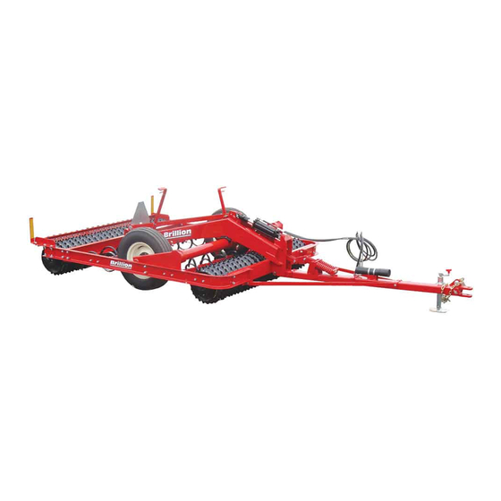
Summary of Contents for Landoll Brillion M881
- Page 1 Transport Pulvi-Mulcher Models - M881,MC881,MCC881, MS881,MCS881,MCCS881 Operator’s Manual LANDOLL CORPORATION 1900 North Street Marysville, Kansas 66508 (785) 562-5381 800-428-5655 ~ WWW.LANDOLL.COM 1092rev601 2K795...
-
Page 3: Table Of Contents
Table of Contents Introduction and Safety Information Introduction ..............1-1 Description of Unit . - Page 4 Operation Tractor Preparation ............3-1 Pulvi-Mulcher Preparation .
-
Page 5: Introduction And Safety Information
Failure to comply with this warning can result in within 10 days of retail purchase, using the Landoll to the personal injury or death, damage Corporation Ag Products on-line registration process. -
Page 6: Safety
INTRODUCTION AND SAFETY INFORMATION Safety When applying decals to the implement, be sure to clean the surface to remove any dirt or residue. Where possible, sign placement should protect the sign from NOTE abrasion, damage, or obstruction from mud, dirt, oil etc. Investigation has shown that nearly 1/3 of all farm ... -
Page 7: Maintenance Safety
INTRODUCTION AND SAFETY INFORMATION Maintenance Safety High Pressure Fluid Safety • Block the implement so it will not roll when working on Escaping fluid under pressure can be nearly invisible and or under it to prevent injury. have enough force to penetrate the skin causing serious injury. -
Page 8: Safety Chain
INTRODUCTION AND SAFETY INFORMATION Safety Chain Attach the chain to the tractor drawbar support or specified anchor location. Never attach the chain to an Use a safety chain to help control drawn machinery intermediate support. Allow only enough slack in the should it separate from the tractor drawbar. -
Page 9: Safety Decals
INTRODUCTION AND SAFETY INFORMATION Safety Decals Figure 1-3: Safety Decals 2K795... - Page 10 INTRODUCTION AND SAFETY INFORMATION Figure 1-4: Decal Locations 2K795...
-
Page 11: Assembly
Chapter 2 Assembly Frame Assembly CAUTION Do not work on or under this machine unless NOTE securely blocked and supported by a hoist or Use bevel washers where the bolts pass through channel tractor or by other sufficient means. flanges. -
Page 12: Rollers To Frame
ASSEMBLY Rollers to Frame Figure 2-2: Rollers to Frame 2K795... -
Page 13: Center Truss
ASSEMBLY Center Truss Figure 2-3: Center Truss 2K795... -
Page 14: Attaching The Rockshaft
ASSEMBLY Attaching the Rockshaft NOTE Make sure the mounting surfaces are free of rust or dirt. Attach the Rockshaft to the Center Truss by place the Bearing Cap on top and on each side of the Rockshaft Lug. Place LH and RH Axle Supports onto each end of the Rockshaft. - Page 15 ASSEMBLY Figure 2-5: Rockshaft 2K795...
-
Page 16: Drawbar Installation
ASSEMBLY Drawbar Installation Drawbar is attached to the frame with 1 x 7-7/16 Mounting Pin, secure with 1/4 x 1-1/2 Cotter Pins. Attach Drawbar Braces to the Frame by inserting pivot bushing into the reinforced portion of the brace and placing brace between the frame bottom angles,... - Page 17 ASSEMBLY Figure 2-6: Drawbar 2K795...
-
Page 18: Drawbar Linkage
ASSEMBLY Drawbar Linkage When making the final connection, the drawbar may need to be blocked up a few inches for easier assembly. Insert 2 x 36-1/4 Straps through the front of the Truss and Turn the 3/4-10 x 10 Bolt into or out of the yoke to level position a strap on each side of the Rockshaft Lug the Pulvi-Mulcher. -
Page 19: Transport Lock Installation
ASSEMBLY Transport Lock Installation secure with 3/4 x 2-3/4 Clevis Pin, Flat Washers and 5/32 x 1-1/2 Cotter Pin. Install Transport Bracket to the rear of the Truss with Thread 3/8-16 Nut approximately 2” from the bottom of 1/2-13 x 1-1/2 Bolts, Lockwashers and Nuts and to the 3/8-16 x 3 Bolt head. -
Page 20: Hydraulics Installation
ASSEMBLY Hydraulics Installation Purging the Hydraulic System WARNING WARNING Escaping fluid under pressure can be nearly Escaping hydraulic fluid can cause serious invisible and have enough force to penetrate the personnel injury. Relieve system pressure before skin causing serious injury. Use a piece of repairing, adjusting, or disconnecting. - Page 21 ASSEMBLY Figure 2-10: Hydraulics 2K795 2-11...
- Page 22 ASSEMBLY Table provided for general use. NOTES: 2-12 2K795...
-
Page 23: Tooth Mounting Dimensions
ASSEMBLY Tooth Mounting Dimensions Figure 2-11: Tooth Mounting Dimensions 2K795 2-13... -
Page 24: Tooth Control Installation
ASSEMBLY Tooth Control Installation Mark the tubes for Teeth/Tine locations prior to installing the tubes. See Figure 2-11. Do Not Install Teeth/Tines at this time. NOTE The Control Brackets are mounted in different positions based on the tine. C-Tooth Installation Slide the Front Spring Tooth Support, making certain that the 5 inch width of the support is toward the rear of machine... - Page 25 ASSEMBLY Figure 2-13: Front C-Tooth Figure 2-14: Rear C-Tooth 2K795 2-15...
-
Page 26: S-Tine Installation
ASSEMBLY S-Tine Installation Slide the Front Spring Tooth Support, making certain that the 5 inch width of the support is toward the rear of machine and slide the Control Bracket (square hole is straight) onto the left side of the front Tooth Tube. - Page 27 ASSEMBLY Figure 2-17: Front S-Tine Figure 2-18: Rear S-Tine 2K795 2-17...
-
Page 28: Rear Scraper Installation
ASSEMBLY Rear Scraper Installation Bolts, Beveled Washers, Flat Washer, Lockwasher and Nut. See Figure 2-19. With the Rollers on level ground, place the scraper bar Attach the Scrapers to the bar so that there is a 1/4” gap on top of the frame side channels. Place a Decal Bracket between the wheel and scraper with 3/8-16 x 1-1/2 Car- on each side over the Scraper Bar mounting hole. -
Page 29: Front Scrapers - Optional
ASSEMBLY Front Scrapers - Optional Support Center with 1/2-13 x 1-1/2 Bolts, Lockwashers and Nuts. See Figure 2-20. Position the Scraper Bar LH and Scraper Bar RH under Attach the Scrapers to the bar so that there is a 1/4” gap the Truss, between the Frame side channel and the Front between the wheel and scraper with 3/8-16 x 1-1/2... -
Page 30: Land Leveler - Optional
ASSEMBLY Land Leveler - Optional Attach the eight leveler supports to the front frame using 1/2-13 x 2 Bolts, Lockwashers and Nuts. Position Leveler Angle in front of Leveler Supports align holes and secure with 1/2-13 x 2 Bolts, Lockwashers and Nuts. See Figure 2-21. -
Page 31: Operation
Chapter 3 Operation Tractor Preparation DANGER The M881 Pulvi-Mulcher is designed to be pulled by Never allow anyone to ride on the M881 tractor equipped with a drawbar. Pulvi-Mulcher at any time. Allowing a person to Before attaching the implement, prepare the tractor as ride on the machine can inflict serious personal follows: injury or death to that person. -
Page 32: Hydraulic Cylinder Hook Up
OPERATION Hydraulic Cylinder Hook Up If machine is lowered, the only difference is make sure transport lock straps are in storage position. Ensure 1/2 x For instances where the cylinder stays with the tractor, 2-1/2 Clevis Pin is locking Float Link See Figure 3-7. not the implement;... -
Page 33: Hydraulic Lift System
OPERATION Hydraulic Lift System The M881Pulvi-Mulcher is equipped with a hydraulic lift system. A hydraulic cylinder is used on the rockshaft. Figure 3-2: Hydraulic Leak Detection WARNING Escaping hydraulic fluid can cause serious personnel injury. Relieve system pressure before repairing, adjusting, or disconnecting. -
Page 34: C-Tooth Adjustment
OPERATION C-Tooth Adjustment NOTE The working depth of the spring teeth is controlled by the Keep in mind that the tines will spring back, so the hand lever on each tooth bar. Adjustments range from maximum depth will vary depending on the soil type. having the teeth clear of ground when using the machine ... -
Page 35: S-Tine Adjustment
OPERATION S-Tine Adjustment CAUTION The working depth of the spring teeth is controlled by the hand lever on each tooth bar. Adjustments range from Do Not Attempt to remove pin connecting having the teeth clear of ground when using the machine cylinder to rockshaft if there is any load on as a pulverizer, to a maximum working depth of 8 inches. -
Page 36: Spring Adjustment
OPERATION Spring Adjustment During the raising cycle, the springs are used to force the rear of the machine to lift before the front, preventing a jolt when it shifts from rear heavy to front heavy. Tighten springs only to the level needed to accomplish this. Figure 3-5: Spring Adjustment 2K795... -
Page 37: Transport Lock
OPERATION Transport Lock Road to Field: To prepare for field operation, remove the Transport Lock Straps from the Rockshaft Lug by Field to Road: To prepare for transport, remove the Pin removing the Pin and Hairpin and moving the Straps on and Hairpin from the Transport Lock Straps and move the each side of the Bolt on the left of the center truss. -
Page 38: Scraper Adjustment
OPERATION Scraper Adjustment Scrapers are optional on notched front rollers. Adjustment procedure is the same for the front. The Pulvi-Mulcher, if equipped with notched rear wheels will have scrapers. To adjust scrapers; lower machine on level surface. Adjust scrapers to 1/4” gap between scraper and wheel. -
Page 39: Transport
OPERATION Transport 1. Check and follow all federal, state, and local requirements before transporting the Pulvi-Mulcher. 2. The Pulvi-Mulcher should be transported only by tractor required for field operation. The implement weight should not exceed more than 1.5 times the tractor weight. - Page 40 OPERATION 11. Transport during daylight hours when ever possible. Make sure SMV emblem is clearly visible and operating. Remove any obstructions such as dirt, mud, stalks or residue that restricts view before transporting. See Figure 3-11. Figure 3-11: SMV Sign 3-10 2K795...
-
Page 41: Maintenance
Chapter 4 Maintenance General Torque Specifications (rev. 4/97) This chart provides tightening torques for general purpose applications when special torques are not specified on process or drawing. Assembly torques apply to plated nuts and capscrews assembled without supplemental lubrication (as received condition). They do not apply if special graphite moly-disulfide or other extreme pressure lubricants are used. -
Page 42: Hydraulic Fitting Torque Specifications
MAINTENANCE Hydraulic Fitting Torque Specifications 37 degree JIC, ORS, &ORB (REV. 10/97 This chart provides tightening torques for general purpose applications when special torques are not specified on process or drawing. Assembly torques apply to plated nuts and capscrews assembled without supplemental lubrication (as received condition). They do not apply if special graphite moly-disulfide or other extreme pressure lubricants are used. -
Page 43: Tires
Seal kits are available from your Wheel bearing maintenance should be performed at the Brillion/Landoll dealer. beginning of every season of use. Check the wheel bearings periodically for excessive end play. If needed, 3. - Page 44 MAINTENANCE Figure 4-2: Lubrication Points and Intervals 2K795...
-
Page 45: Clamp Tightening Procedure
MAINTENANCE Clamp Tightening Procedure If the axle has an internal bearing, check that it turns freely. You should be able to turn the bearing with your The tightening procedure and torque requirement is fingers. If rotation is jerky, loosen set screws and U-bolt critical in keeping in keeping the clamp tight and also has until bearing turns smoothly. -
Page 46: C-Tooth Point Replacement
MAINTENANCE C-Tooth Point Replacement Place the reversible point on the front of the C-tooth, line-up the two bolt holes, insert two 3/8-16 X 1-3/4 As the C-tooth point wears, a replacement reversible Cultivator Bolts and tighten using two 3/8-16 Flanged point is available for installation. - Page 47 MAINTENANCE 2K795...
- Page 48 MAINTENANCE Table provided for general use. NOTES: 2K795...
-
Page 49: General Reference And Specifications
Chapter 5 General Reference and Specifications M881, MC881, MCC881 MS881, MCS881, MCCS881 M881: 2,934 lbs. (1,302 kg) MS881: 2,944 lbs. (1,325 kg) Approximate Weight MC881: 2,824 lbs. (1,271 kg) MCS881: 2,841 lbs. (1,266 kg) MCC881: 2,739 lbs. (1,233 kg) MCCS881: 2,724 lbs. (1,226 kg) Working Width 7 ft. - Page 50 GENERAL REFERENCE AND SPECIFICATIONS Table provided for general use. NOTES: 2K795...
- Page 51 Document Control Revision Log: Date Revision Improvement(s) Description and Comments Team Member 06/2017 Initial Release...
- Page 52 Equipment from Landoll Corporation is built to exacting standards ensured by ISO 9001 registration at all Landoll manufacturing facilities. Pulvi-Mulcher Models - M881,MC881,MCC881, MS881,MCS881,MCCS881 Operator’s Manual Re-Order Part Number 2K795 LANDOLL CORPORATION 1900 North Street Marysville, Kansas 66508 (785) 562-5381 800-428-5655 ~ WWW.LANDOLL.COM...
Need help?
Do you have a question about the Brillion M881 and is the answer not in the manual?
Questions and answers