Advertisement
Quick Links
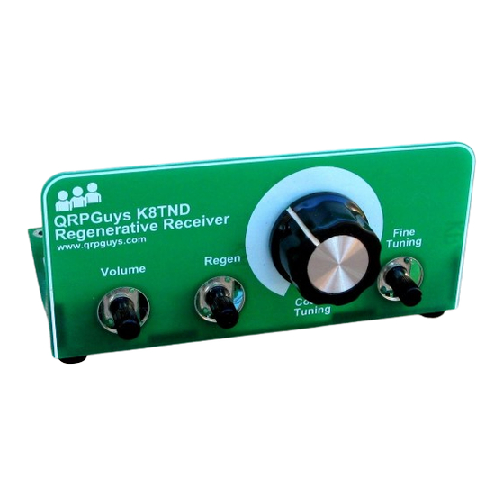
QRPGuys K8TND Regenerative Receiver
First, familiarize yourself with the parts and check for all the components. If a part is missing, please
contact us at
qrpguys.parts@gmail.com
and we will send you one.
Please read all the instructions before starting to assemble the receiver.
Parts List
1 – QRPGuys K8TND Regen Receiver PCB, 4 pieces
1 – U1, LM386 DIP IC
1 – Q1, 2N3904 transistor
1 – Q2, J310 FET
1 – D1, 1N4001-7 diode, black, silver band on one end
1 – D2, ISV149 varactor diode
1 – D3, 1N4737A, 7.5V zener diode, small glass, band on one end
1 - D4, high intensity led
1 – R1, 2.2K resistor (red-red-red-gold)
2 - R2,8, 1 meg ohm resistor (brown-black-green-gold)
3– R3,7,11 10K resistor (brown-black-orange-gold)
1 – R4, 5.6K resistor (green-blue-red-gold)
1 – R5, 1K resistor (brown-black-red-gold)
1 – R6, 10 ohm resistor (brown-black-black-gold)
1 – R9, 51 ohm resistor (green-brown-black-gold)
1 – R10, 4.7k ohm (yellow-violet-red-gold)
7 – C1,2,5,7,11,12,15, .01uF mono capacitor, marked 103
1 – C3, 560pF NP0/C0G capacitor, marked 561
Page 1 of 10
regen_100418.pdf
Advertisement

Related Manuals for QRPGuys K8TND


Summary of Contents for QRPGuys K8TND
- Page 1 Please read all the instructions before starting to assemble the receiver. Parts List 1 – QRPGuys K8TND Regen Receiver PCB, 4 pieces 1 – U1, LM386 DIP IC 1 – Q1, 2N3904 transistor 1 – Q2, J310 FET 1 –...
-
Page 2: Front Panel
1 – C4, 100pF capacitor, marked 101 1 – C6, .001uF mono capacitor, marked 102 1 – C8, 470pF NP0/C0G capacitor, marked 471 1 – C9, 4.7uF electrolytic capacitor 2 – C10,14, 100uF electrolytic capacitor 1 – C13, 1uF electrolytic capacitor 3 –... - Page 3 On all the mechanical assembly soldering, you will use the same technique. You tack a single tiny point first, and then check to see that it is square and aligned with the registration points and assembly notes. It is easy to re-heat the joint and adjust the alignment when there is only a single point.
- Page 4 Position either of the side gussets against the inside edge of the previous assembly. Match the letters. You can hold the small triangle of PCB material while you put a small “tack” on one of the pads. As before, check for squareness, and a flush joint. See the figure below. “Tack”...
- Page 5 Install VR 2,3,4, 10K pcb mounted potentiometer Install R1, 2.2K resistor (red-red-red-gold) Install R2,8, 1 meg ohm resistor (brown-black-green-gold) Install R3, 7,11, 10K resistor (brown-black-orange-gold) Install R4, 5.6K resistor (green-blue-red-gold) Install R5, 1K resistor (brown-black-red-gold) Install R6, 10 ohm resistor (brown-black-black-gold) Install R9, 51 ohm resistor (green-brown-black-gold) Install R10, 4.7k ohm (yellow-violet-red-gold) Install RFC1, 1mH molded inductor, marked (brown-black-red-silver)
- Page 6 Install C13, 1uF electrolytic capacitor, observe polarity, the long lead is positive Install J1, DC power jack Install 9V battery clip-female, as shown below Install 9V battery clip-male, as shown below Install VR1, 10K panel mount pot. Connect to the pcb using the hook-up wire provided as shown below.
- Page 7 Now is a good time to mention a good way for counting the turns on your toroids. Many times on Note: a toroid with a lot of turns, you can lose track going around, as some are quite small. A good trick is to take a digital picture of it before you trim the leads and enlarge it on your computer screen.
- Page 8 Install the antenna and ground connection hardware as shown in the graphic below. Next, power up the receiver with a 9V battery or 12V via the DC power jack. Anytime the 12V power jack is used, be sure to remove the 9V battery. The center pin is“+”...
- Page 9 Schematic: Page 9 of 10 regen_100418.pdf...
- Page 10 Notes: __________________________________________________ __________________________________________________ __________________________________________________ __________________________________________________ __________________________________________________ __________________________________________________ __________________________________________________ __________________________________________________ __________________________________________________ __________________________________________________ __________________________________________________ __________________________________________________ Page 10 of 10 regen_100418.pdf...
Need help?
Do you have a question about the K8TND and is the answer not in the manual?
Questions and answers