Table of Contents
Advertisement
Quick Links
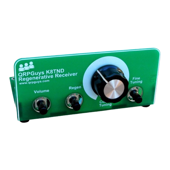
QRPGuys K8TND VHF Regenerative Receiver for AM Aircraft Band
First, familiarize yourself with the parts and check for all the components. If a part is missing, please
contact us at
qrpguys.parts@gmail.com
and we will send you one.
Please read all the instructions before starting to assemble the receiver.
Parts List
1 – QRPGuys K8TND VHF Regenerative Receiver PCB
1 – U1, LM386 DIP IC
1 – Q1, BF199 transistor
1 – D1, BB910 varactor diode
1 – D2, green LED
1 – R1, 4.7K resistor (yellow-violet-red-gold)
1 – R2, 1K resistor (brown-black-red-gold)
1 – R3, 1M ohm resistor (brown-black-green-gold)
1 – R4, 39K resistor (orange-white-orange-gold)
1 – R5, 15K resistor (brown-green-orange-gold)
1 – R6, 10K resistor (brown-black-orange-gold)
1 – L1, 2.2uH molded inductor (red-red-gold-silver)
5 – C1,3,5,11,12, .01uF (10nF) mono capacitor, marked 103
Page 1 of 7
airband_111719.pdf
Advertisement
Table of Contents

Related Manuals for QRPGuys K8TND


Summary of Contents for QRPGuys K8TND
- Page 1 QRPGuys K8TND VHF Regenerative Receiver for AM Aircraft Band First, familiarize yourself with the parts and check for all the components. If a part is missing, please contact us at qrpguys.parts@gmail.com and we will send you one. Please read all the instructions before starting to assemble the receiver.
- Page 2 1 – C2, 10pF NP0/C0G capacitor, marked 10 or 100 3 - C4,8,9, 10uF electrolytic capacitor 1 – C6, 100pF NP0/C0G capacitor, marked 101 1 – C10,.001uF (1nF) mono capacitor marked 102 1 – C7, 100uF electrolytic capacitor 3 – VR1,2,3, 10K PCB potentiometer 1 –...
- Page 3 Install R4, 39K resistor (orange-white-orange-gold) Install R5, 15K resistor (brown-green-orange-gold) Install R6, 10K resistor (brown-black-orange-gold) Install L1, 2.2uH molded inductor (red-red-gold-silver) Install 8pin DIP socket Install D1, BB910 varactor diode, polarity sensitive, match the board outline Install D2, green LED, observe polarity, the long lead is positive Install Q1, BF199 transistor, match the board outline...
- Page 4 The last item to install is the T1 air wound transformer. We provide a #10-24 screw to act as a winding form for the coil. It is mounted about a half inch above the surface of the pcb to allow some adjustment of the winding distance between the secondary and primary.
- Page 5 Alignment and Setup: There are three ways to align your K8TND VHF Regenerative Receiver for the AM aircraft band. The "spacing between coils" should be approx.1/8” (3mm). The further the spacing (to a limit), the more selective the receiver will be.
- Page 6 Using a Regeneration (REGEN) control: The REGEN is easy to adjust on this receiver. Turn the control all the way down, counter-clockwise, then slowly turn it clockwise and you'll hear a little "pop", which means the receiver has gone into regeneration.
- Page 7 For experimenters: K8TND has successfully moved the coverage to 6 meters, by changing three components to these values. L1 – 1mH molded inductor R5 – 24K 1/4W resistor T1 secondary as described below. Change the secondary of the transformer to 10 1/2 turns, 26awg magnet wire close wound on a 5mm dia.
Need help?
Do you have a question about the K8TND and is the answer not in the manual?
Questions and answers