Advertisement
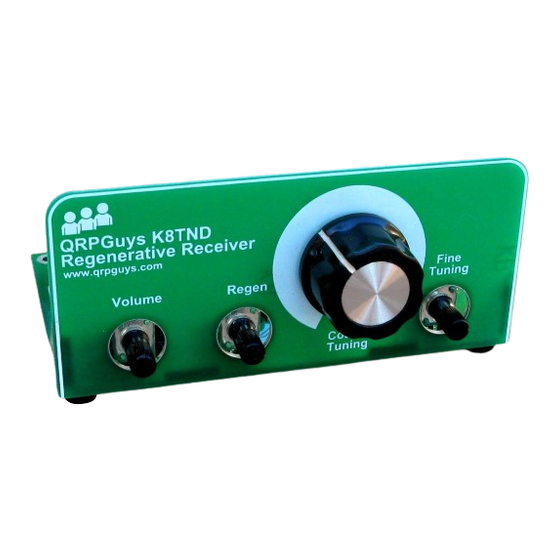
QRPGuys K8TND Direct Conversion Receiver
for 80m or 40m or 30m or 20m
First, familiarize yourself with the parts and check for all the components. If a part is missing, please
contact us at
qrpguys.parts@gmail.com
and we will send you one.
Please read all the instructions before starting to assemble the receiver.
We supply the components for the 40m version. At the end of page 4 there is a table of suggested
values for other bands for those that want to experiment. They are suggested values, and may need
some tweaking for optimum performance
Parts List
1 – Receiver pcb
1 – U1, 78L09 regulator
1 – U2, NE602 or NE612 DIP8 IC
1 – U3, LM386 DIP8 IC
1 - Q1, 2N3904 transistor
1 – D1, 1N4007 diode, black, silver band on one end
1 – D2, 1N4737A, 7.5V zener diode, small glass, black band on one end
2 – D3, BB910 varactor diode
1 – D4, clear lens, red led
1 – D5, high intensity green led
2 – R1,6, 10 ohm resistor (brown-black-black-gold)
1 - R2, 47K resistor (yellow-violet-orange-gold)
2 – R3,9, 220 ohm resistor (red-red-brown-gold)
1 – R4, 22K resistor (red-red-orange-gold)
1 – R5, 390K resistor (orange-white-yellow-gold)
Page 1 of 8
dc_102019.pdf
Advertisement
Table of Contents

Related Manuals for QRPGuys K8TND


Summary of Contents for QRPGuys K8TND
- Page 1 QRPGuys K8TND Direct Conversion Receiver for 80m or 40m or 30m or 20m First, familiarize yourself with the parts and check for all the components. If a part is missing, please contact us at qrpguys.parts@gmail.com and we will send you one.
- Page 2 2 – R7,8, 470 ohm resistor (yellow-violet-brown-gold) 1 – R11, not used 3 – VR1,2,3, 10K pcb mounted potentiometer 9 - C1,4,8,11,12,13,14,19,21, .1uF mono capacitor marked 104 3 - C2,18,20, 100uF electrolytic capacitor 1 – C9, .001uF mono capacitor marked 102 4 –...
- Page 3 Install R4, 22K resistor (red-red-orange-gold) Install R5, 390K resistor (orange-white-yellow-gold) Install R7,8, 470 ohm resistor (yellow-violet-brown-gold) Install R11, not used Install L2, 1mH molded choke marked (brown-black-red-silver), do not confuse with resistor Install C1,4,8,11,12,13,14,19,21, .1uF mono capacitor marked 104 Install C9, .001uF mono capacitor marked 102 Install C3,5,6,7, 100pF NP0/C0G capacitor marked 101 Install C10, 680pF NP0/C0G capacitor marked 681 Install C22, 620pF mono capacitor marked 681 for 80m, 120pF mono capacitor marked 121 for...
- Page 4 Install Q1, 2N3904 transistor Install J2, 3.5mm stereo jack Install J1, DC power jack Install C2,18,20, 100uF electrolytic capacitor, observe polarity, the long lead is positive Install C15,16, 10uF electrolytic capacitor, observe polarity, the long lead is positive Install J3, horz. pcb BNC female jack Use the T50-2 toroid core (red), wind T1 as shown below, use 36”...
- Page 5 The L1 position is set up for either a T50 or T68 size core. Push 1” of the wire down the hole from the top and hold it, feed the remaining turns up from the bottom. Wind CCW, Every time the wire goes thru the center counts as one turn.
- Page 6 Retain T1and L1 with the nylon hardware as shown in the graphic below. Feed the screw from under the pcb. Install VR1,2,3, 10K pcb mounted potentiometers Attach the four self adhesive rubber feet to the corners on the bottom of the board where indicated by the silkscreen.
- Page 7 Schematic: Page 7 of 8 dc_102019.pdf...
- Page 8 Notes: __________________________________________________ __________________________________________________ __________________________________________________ __________________________________________________ __________________________________________________ __________________________________________________ __________________________________________________ __________________________________________________ __________________________________________________ __________________________________________________ __________________________________________________ __________________________________________________ Page 8 of 8 dc_102019.pdf...
Need help?
Do you have a question about the K8TND and is the answer not in the manual?
Questions and answers