Spectrum Digital eZdsp TMS320C5515 Technical Reference
Usb stick
Hide thumbs
Also See for eZdsp TMS320C5515:
- Quick start manual (9 pages) ,
- Technical reference (40 pages)
Advertisement
Quick Links
Advertisement

Related Manuals for Spectrum Digital eZdsp TMS320C5515


Summary of Contents for Spectrum Digital eZdsp TMS320C5515
- Page 1 TMS320C5515 eZdsp USB Stick Technical Reference 2010 DSP Development Systems...
- Page 3 TMS320C5515 eZdsp USB Stick Technical Reference 512845-0001 Rev A February 2010 SPECTRUM DIGITAL, INC. 12502 EXCHANGE DRIVE, #440 STAFFORD, TX. 77477 Tel: 281.494.4500 FAX: 281.494.5310 sales@spectrumdigital.com www.spectrumdigital.com...
-
Page 4: Important Notice
Please be aware that the products described herein are not intended for use in life-support appliances, devices, or systems. Spectrum Digital does not warrant nor is liable for the product described herein to be used in other than a laboratory development environment. Use in any other environment voids the warranty. - Page 5 Contents Introduction to the TMS320C5515 eZdsp USB Stick ..... Provides a description of the TMS320C5515 eZdsp USB Stick, and key features. Overview of the TMS320C5515 eZdsp USB Stick .
- Page 6 About This Manual This document describes the board level operations of the TMS320C5515 eZdsp USB Stick. The Stick is based on the Texas Instruments TMS320C5515 Digital Signal Processor (DSP). The TMS320C5515 eZdsp USB Stick is a USB based printed circuit board (PCB) that allows engineers and programmers to evaluate certain characteristics of the TMS320C5515 DSP.
- Page 7 Chapter 1 Introduction to the TMS320C5515 eZdsp USB Stick This chapter provides you with an overview of the C5515 eZdsp USB Stick along with the key features. Topic Page 1.0 Overview of the TMS320C5515 eZdsp USB Stick 1.1 Key Features of the TMS320C5515 eZdsp USB Stick 1.2 C5515 eZdsp USB Stick Block Diagram 1.3 C5515 eZdsp Memory Map 1.4 C5515 eZdsp I...
- Page 8 Spectrum Digital, Inc 1.0 Overview of the C5515 eZdsp USB Stick The C5515 eZdsp USB Stick is an evaluation tool for the Texas Instruments TMS320C5515 Digital Signal Processor (DSP). This USB bus powered tool allows the user to evaluate the following items: •...
- Page 9 Spectrum Digital, Inc 1.1 Key Features of the C5515 eZdsp USB Stick The C5515 eZdsp USB Stick has the following features: • Texas Instrument’s TMS320C5515 Digital Signal Processor • Texas Instruments TLV320AIC3204 Stereo Codec (stereo in, stereo out) • Micro SD connector •...
-
Page 10: Memory Blocks
Spectrum Digital, Inc 1.3 C5515 eZdsp Memory Map The C5515 eZdsp supports on chip DARAM, and off chip NOR Flash. The addressing for each of these memory blocks is shown in the figure below. CPU Byte Address MEMORY BLOCKS 000000h... -
Page 11: Physical Description
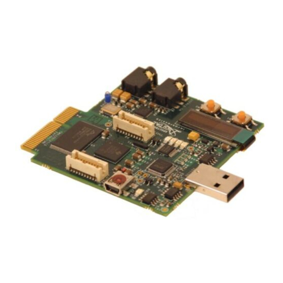
Chapter 2 Physical Description This chapter describes the physical layout of the TMS320C5515 eZdsp USB Stick. Topic Page 2.0 Board Layout 2.1 Connector Index 2.1.1 J1, C5515 USB Connector 2.1.2 J2, XDS100 USB Connector 2.1.3 J3, Audio In Connector 2.1.4 J4, Audio Out Connector 2.1.5 J5, LCD Interface 2.1.6 J6, Micro SD Connector 2.1.7 P1, P2, Bluetooth Board Interface... - Page 12 Spectrum Digital, Inc 2.0 Board Layout The C5515 eZdsp USB Stick is a 2.85 x 2.65 inch six (6) layer printed circuit board which is powered off the USB bus of personal computer or laptop computer. This means this board does not require an external power supply.
- Page 13 Spectrum Digital, Inc 2.1 Connector Index The C5515 eZdsp USB Stick has nine (9) connectors which provide the user access to various signals on the C5515 Stick. These connectors are shown in the table below. Table 1: C5515 eZdsp USB Stick Connectors...
- Page 14 Spectrum Digital, Inc 2.1.2 J2, XDS100 USB Connector The USB connector, J2, is used to attach the C5515 eZdsp stick to a personal computer or laptop. The signals on the pins of this connector are shown below. Table 4: J2, XDS100 USB Connector...
- Page 15 Spectrum Digital, Inc 2.1.4 J4, Audio Out Connector The Audio Out connector, J4, is used to bring signals from the TLP320AIC3204 codec. The signals on the pins of this connector are shown below. Table 6: J4, Audio Out Connector Pin #...
- Page 16 Spectrum Digital, Inc 2.1.5 J5, LCD Interface Connector, J5, is used to interface to an LCD character display. The signals on the pins of this connector are shown below. Table 7: J5, LCD Interface Pin # Signal Name VBAT VBREF...
- Page 17 Spectrum Digital, Inc 2.1.7 P1, P2, Bluetooth Board Interface Connectors P1, and P2 are expansion connectors used to provide an interface to a Bluetooth board. The signals on the pins of these connectors are shown in the tables below. Table 9: P1, Bluetooth Board Interface...
- Page 18 Spectrum Digital, Inc 2.1.8 P4, Expansion Connector The Expansion connector, P4, is used to bring signals from C5515 DSP out to a connector for user interface. This card edge connector has all of the odd number (1,3,...,59) tabs on the top side of the board and all of the even number tabs (2,4,...,46) on the bottom side of the board.
- Page 19 Spectrum Digital, Inc The table below lists the signals that appear on each of the tabs of connector P1. The signals on the pins of this connector are shown below. Table 11: P4, Expansion Connector Pin # Pin # Signal Name...
- Page 20 Spectrum Digital, Inc 2.2 System LEDs The C5515 eZdsp USB Stick has 5 Light Emitting Diodes (LED). These LEDs are under the application software control running on the C5515 processor. These LEDs are shown in the table below. Table 12: System LEDs...
- Page 21 Spectrum Digital, Inc 2.5 Test Points The C5515 eZdsp USB Stick has six (6) test points for the monitoring of signals. The location of the test points are shown in the figure below. Figure 2-6, C5515 eZdsp USB Stick (top) The signals on the test points are shown in the table below.
- Page 22 Spectrum Digital, Inc 2-12 TMS320C5515 eZdsp USB Stick Technical Reference...
- Page 23 Appendix A Schematics This appendix contains the schematics for the TMS320C5515 eZdsp USB Stick.
- Page 24 10 - AUDIO CODEC 11 - LCD/USER LEDS/SWITCHES 12 - EXPANSION CONNECTOR 13 - XDS100 INTERFACE REVISION STATUS OF SHEETS DATE SHEET R.R.P. 10/15/2009 DATE SPECTRUM DIGITAL INCORPORATED T.W.K. 10/15/2009 ENGR DATE TMS320C5515 EZDSP MODULE SHEET R.R.P. 10/15/2009 Title: ENGR-MGR DATE R.R.P.
- Page 25 SPI_CS2 12 LCD_RW_WRB/SPI_CS2 SPI_CS3 SPI_CS3 12 LCD_RS/SPI_CS3 VDD_IO1 DVDDIO DVDDIO TMS320C5515 I2C_SDA 7,10,11,12 I2C_SDA I2C_SCL 7,10,11,12 I2C_SCL SPECTRUM DIGITAL INCORPORATED Title: TMS320C5515 EZDSP MODULE Page Contents: GPIO,MMC-SD,SPI,I2C,I2S Revision: Size: DW G NO 512842-0001 Date: W ednesday, February 17, 2010 Sheet...
- Page 26 RF1 = ( Vout/Vref - 1) * RF2 TARGET_TDO 13 RF1 = ( 1.3/1.224 - 1) * 169K 169K TARGET_TDI 13 TARGET_TMS 13 TARGET_TRSTn 13 SPECTRUM DIGITAL INCORPORATED TMS320C5515 EZDSP MODULE Title: Page Contents: CLOCK,JTAG,USB Revision: Size: DW G NO...
- Page 27 EM_WEn EM_WAIT4 EM_WAIT4 EM_WAIT5 EM_WAIT5 EM_OEn EM_CS2n EM_CS2n EM_CS2n 6 EM_CS3n EM_CS4n DVDDEMIF EM_CS5n NO-POP TMS320C5515 SPECTRUM DIGITAL INCORPORATED Title: TMS320C5515 EZDSP MODULE Page Contents: TMS320C5515 EMIF Revision: Size: DW G NO 512842-0001 Date: W ednesday, February 17, 2010 Sheet...
- Page 28 VSS.18 LDO_EN VSS.19 VSSA_ANA.1 VSS.20 POR_BGRST 0.1uF VSSA_ANA.2 VSS.21 AGND PM_CTL TMS320C5515 RSV6 AGND AGND BLM18AG601SN1D SPECTRUM DIGITAL INCORPORATED AGND Title: TMS320C5515 EZDSP MODULE Page Contents: TMS320C5515 POWER Revision: Size: DW G NO 512842-0001 Date: Monday, February 22, 2010 Sheet...
- Page 29 DQ14 D 15 DQ15/A-1 (RY/BY#(A19) EM_WAIT2 4 A20(NC_L016) A21(NC_L016_L032) VDD_IO2 EM_CS2n EM_CS2n TARGET_PWR_GOOD 2,9,10,11,13 TARGET_PWR_GOOD RESET S29AL032D70TFI04 SPECTRUM DIGITAL INCORPORATED Title: TMS320C5515 EZDSP MODULE Page Contents: NOR FLASH Revision: Size: DW G NO 512842-0001 Date: Wednesday, February 17, 2010 Sheet...
- Page 30 I2S1_CLK UART_CTS 2,12 I2S2_DX I2S2_DX 2,12 2,8,12 SD_CMD GPIO13 2,12 I2S2_RX I2S2_RX 2,12 HEADER 10X2 HEADER 10X2 SPECTRUM DIGITAL INCORPORATED Title: TMS320C5515 EZDSP MODULE Page Contents: CC BOARD INTERFACE Revision: Size: DW G NO 512842-0001 Date: Wednesday, February 17, 2010...
- Page 31 2,7,12 SD_CMD DAT3 SD_CLK 2,7,12 SD_CLK INSERT_COM SD_DATA0 2,7,12 SD_DATA0 DAT0 SD_DATA1 2,7,12 SD_DATA1 DAT1 MicroSD_CARD SPECTRUM DIGITAL INCORPORATED Title: TMS320C5515 EZDSP MODULE Page Contents: MMC/SD SOCKETS Revision: Size: DW G NO 512842-0001 Date: W ednesday, February 17, 2010 Sheet...
- Page 32 VCC_3V3 VCCUSB FTDI_3V3 OUT1 OUT2 4.7uF 4.7uF .1uF 220K 4.7uF TPS76601 294K 1% 169K 1% TARGET_PWR_GOOD 2,6,10,11,13 SPECTRUM DIGITAL INCORPORATED Title: TMS320C5515 EZDSP MODULE Page Contents: POWER MANAGEMENT Revision: Size: DW G NO 512842-0001 Date: Wednesday, February 17, 2010 Sheet...
- Page 33 GND-AIC CLK_12MHZ 4.7K USB_CLK_12MHZ NO-POP CPU_CLK_12MHZ Select Internal LDO VDD_IO1 V3.3A BLM21AG151SN1D SPECTRUM DIGITAL INCORPORATED Tie Analog Power to Digital Power through single point connection or Ferrite Bead. Title: TMS320C5515 EZDSP MODULE Page Contents: CODEC BLM21AG151SN1D Revision: Size: DW G NO...
- Page 34 NO-POP 2.2uH MBR0520 C101 1.6M 1% 10pF SN74LV125 LED3 2,12 GPIO17 10uF,16V 10uF 180K TPS61041 SPECTRUM DIGITAL INCORPORATED 2,7,12 GPIO12 Title: TMS320C5515 EZDSP MODULE Page Contents: LCD INTERFACE Revision: Size: DW G NO 512842-0001 Date: Wednesday, February 17, 2010 Sheet...
- Page 35 SPI_TX 2,7,11 GPIO14 SPI_TX 2 GPIO12 SPI_CLK 2,7,11 GPIO12 SPI_CLK 2 GPIO13 SPI_CS1 GPIO13 SPI_CS1 2 SPECTRUM DIGITAL INCORPORATED Title: TMS320C5515 EZDSP MODULE Page Contents: EXPANSION CONNECTORS Revision: Size: DW G NO 512842-0001 Date: W ednesday, February 17, 2010 Sheet...
- Page 36 BCBUS0 EECS BCBUS1 BCBUS2 EESK BCBUS3 EEDATA SI/WUB TEST PWREN# VCCUSB EECS EESK EEDATA SPECTRUM DIGITAL INCORPORATED DOUT 100nF 93C46_56_66 Title: TMS320C5515 EZDSP MODULE Page Contents: XDS100 INTERFACE Revision: Size: DW G NO 512842-0001 Date: Wednesday, February 17, 2010 Sheet...
-
Page 37: Mechanical Information
Appendix B Mechanical Information This appendix contains the mechanical information about the TMS320C5515 eZdsp USB Stick. - Page 38 Spectrum Digital, Inc TMS320C5515 eZdsp USB Stick Technical Reference...
- Page 40 Printed in U.S.A., February 2010 512845-0001 Rev A...
Need help?
Do you have a question about the eZdsp TMS320C5515 and is the answer not in the manual?
Questions and answers