Table of Contents
Advertisement
Quick Links
Advertisement
Table of Contents

Related Manuals for Novation Peak


Summary of Contents for Novation Peak
-
Page 2: Copyright And Legal Notices
Disclaimer Novation has taken all possible steps to ensure that the information given here is both correct and complete. In no event can Novation accept any liability or responsibility for any loss or damage to the owner of the equipment, any third party, or any equipment which may result from use of this manual or the equipment which it describes. -
Page 3: Table Of Contents
Envelopes And Amplifier ..........15 System Updates using Novation Components....... .37 Attack Time . -
Page 4: Introduction
Power Requirements • Kensington Security Slot Peak is shipped with an external 12 V DC, 1 A power supply. This is a “universal” type, and will operate on all mains voltages between 100 V and 240 V. About This Manual The centre pin of the coaxial connector is the positive (+ve) side of the supply. -
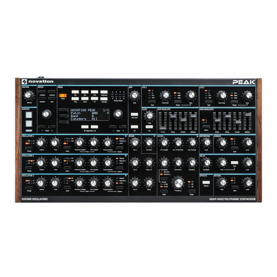
Page 5: Hardware Overview
HARDWARE OVERVIEW Top Panel Peak’s control surface is divided logically into functional areas, with signal generation and treatment broadly following a left-to-right sequence. PATCH MENU LFO 1 LFO 2 ENVELOPE GLIDE MASTER ANIMATE MOD ENVELOPES OSCILLATOR 1 CHORUS DISTORTION OSCILLATOR 2... - Page 6 26 Mod Envelope controls – an identical set of sliders, adjusting the parameters of the two modulation envelopes (see 27 below). 27 Select – Peak generates two independent Mod Envelopes; this button selects which of these (Mod 1 or Mod 2) the Mod Envelope sliders 26 control.
- Page 7 56 . Pages within each menu may be selected with the two Page/Select buttons (Mod Env 1) and/or the Amp Envelope (Amp Env): note that these two sources may be below the display. Adjusting any of Peak’s rotary controls (except MASTER and PATCH) used simultaneously invokes an alternative display showing the value of the parameter being adjusted until 39 Env depth –...
-
Page 8: Rear Panel
Note that the USB port only carries MIDI data, not audio. 4 MIDI IN, OUT and THRU – standard 5-pin DIN MIDI sockets for connecting Peak to a keyboard or other MIDI-equipped hardware. 5 PEDAL 1 and PEDAL 2 – two 3-pole (TRS) ¼” jack sockets for connection of switch (e.g., sustain) and/or expression pedals. -
Page 9: Getting Started
Peak and another synth such as a Novation Bass Station II. An external modular LFO in a Eurorack could be used to modulate one or more parameters in Peak via the CV connection. All MIDI data gets recorded in the DAW via USB connections. - Page 10 In this example, a Focusrite Clarett audio interface is used to enable “real-world” With the amplifier or mixer off or muted, connect the AC adaptor to Peak 1 , and plug it instruments to be recorded in the DAW as well as synth sounds. A keyboard controller is into the AC mains.
-
Page 11: Menu Navigation
Patch Loading Patches Bank Peak can store 512 Patches in memory, arranged in four Banks of 128; the Banks are designated A to D. Banks A and B are pre-loaded with 256 great factory Patches Utopian Streams especially created for Peak, while Banks C and D are for storing your own Patches and come pre-loaded with the same default “initial”... -
Page 12: Basic Operation - Sound Modification
Basic Operation – sound modification MIDI control Peak has a very high degree of MIDI implementation, and almost every control and synth Once you have loaded a Patch you like the sound of, you can modify the sound in many parameter is able to transmit MIDI data to external equipment, and similarly, the synth may different ways using the synth controls. -
Page 13: Synthesis Tutorial
Harmonic oscilloscope, and they are: Sine waves, Square waves, Sawtooth waves, Triangle waves and Noise. Each of Peak’s Oscillator sections can generate all these waveforms, and can generate non-traditional synth waveforms as well. (Note that Noise is actually generated independently and mixed in with the other waveforms in the Mixer section.) -
Page 14: Sawtooth Waves
Oscillators against each other, which creates a very warm, ‘fat’ sound. Peak’s Mixer allows you to create a sound consisting of the waveforms of Oscillators 1, 2 and 3, a Noise source and the Ring Modulator output, all mixed together as required. -
Page 15: Envelopes And Amplifier
In addition to the traditional low-pass filter type, there are also high-pass and band-pass Frequency KEY "ON" KEY "OFF" types. On Peak, the filter type is selected with the Shape switch 33 . Volume Volume VOLUME A high-pass filter is similar to a low-pass filter, but works in the “opposite sense”, so... -
Page 16: Attack Time
TIME Hold Time This parameter is not found on many synthesisers, but is available on Peak. It determines for how long the note’s volume remains at its maximum level following the Attack Time, Alternatively, if the same LFO signal were to modulate the Filter cut-off frequency instead of before commencing the volume drop set by the Decay Time. -
Page 17: Peak: Simplified Block Diagram
The FX return signal is added back to same point in the signal path. Peak’s Oscillator section consists of three identical oscillators, each with its own set of controls. The following descriptions thus apply equally to any of the oscillators. -
Page 18: Pitch
The degree of modification – or deviation the sound. As with many other aspects of Peak, users will best gain an understanding of from the “classic” waveform type – can be varied both manually and as a modulation. The wavetables by experimenting, and especially by adjusting the Shape Amount control. - Page 19 Vsync may be controlled for any or all oscillators using the Modulation Matrix. See “The Modulation Matrix” on page 26 for details of how to Peak has a dedicated very low frequency oscillator which can be used to apply a very use the Matrix.
-
Page 20: The Lfo Section
The LFO Section The LFO Menu LFO1 and LFO 2 are ‘per voice’. This is a very powerful feature of Peak (and other Novation synthesisers). For example, when an LFO is assigned to create vibrato, and a chord Peak has four Low Frequency Oscillators (LFOs), denoted LFO 1 to LFO 4. The... - Page 21 LFO Slew LFO Common Sync Displayed as: Displayed as: Slew Common Initial value: Initial value: Range of adjustment: 0 to 127 Range of adjustment: Off or On Slew has the effect of modifying the shape of the LFO waveform. Sharp edges become Common Sync is only applicable to polyphonic voices.
-
Page 22: The Mixer Section
The Mixer Section The Envelopes Section Peak generates three envelopes each time a key is pressed, which can be used to modify the synth sound in many ways. The envelope controls are based on the familiar AHDSR concept. KEY “ON”... -
Page 23: The Envelopes Menu
Sustain phase. “Legato” literally means Peak’s Envelope section has two sets of four slider controls, one set for Amp Env, the “smoothly”, and this mode aids this style of playing. -
Page 24: The Filter Section
The sum of the various signal sources created in the mixer is fed to the Filter Section, which Frequency can be used to modify the harmonic content of the Oscillator’s output. Peak’s filter is a traditional analogue design, and has an extensive set of modulation and control options. -
Page 25: Filter Tracking
37 adjusts the degree of distortion treatment applied to the signal. The drive is added before the filter. Peak does not have a dedicated Filter menu, but two further Filter-related parameters – Filter Post Drive and Filter Divergence - are also... -
Page 26: The Modulation Matrix
Depth parameter controls the overall degree of a ‘variable’ and ‘additive’ matrix? modulation. The diagram depicts a single matrix “slot”; Peak has 16 such slots, allowing an enormous range of modulation possibilities. By ‘variable’, we mean that it is not just the routing of a controlling source to a controlled parameter which is defined in each slot, but also the “magnitude”... -
Page 27: Voices
But this does depend on how many voices are assigned to each note – see the Unison parameter in the Voice Menu on page 28). However, if you are controlling Peak from a MIDI sequencer or DAW, it is possible to run Modulation Destination out: sequencers don’t have the human constraint of a finite number of fingers. - Page 28 If set to a value other than zero, Pre-Glide takes priority over Glide, though it does use the voices assigned, Peak’s polyphonic capability may be reduced. With four voices per note, setting of Glide’s Time control 28 to determine its duration. Note that Glide must also only two notes may be played together fully polyphonically, and if further notes are played, be On 29 for Pre-Glide to work.
-
Page 29: The Arpeggiator
A. If Mode is set to Poly 2, the C, E Peak will both transmit MIDI note data from the arpeggiator, and allow the arpeggiator to and G will only be played once, which will leave three voices free for playing a play notes according to received MIDI note data. - Page 30 As well as being able to set the basic timing and mode of the arp sequence (with the or slower by adjusting it. The range is 40 to 240 BPM. If Peak is being synchronised to an ArpMode and SyncRate parameters), you can also introduce further rhythmic external MIDI clock, it will automatically detect the incoming tempo and disable the internal variations with the Rhythm parameter.
-
Page 31: The Effects Section
Feedback control 46 sets the level. This results in multiple echoes, as the delayed signal Peak comes equipped with a sound effects (FX) section. FX can be applied to the sound is further repeated. With Feedback set to zero, no delayed signal at all is fed back, so the synth is generating to add colour and character. - Page 32 Chorus EQ Width Displayed as: Displayed as: LoPass HiPass Width Initial values: Initial value: Range of adjustment: 0 to 127 0 to 127 Range of adjustment: 0 to 127 The LoPass and HiPass parameters adjust simple HF and LF filters within the Chorus The Width parameter is only really relevant to settings of LR Ratio which result in processor.
- Page 33 FX Modulation Matrix is effectively an extension of Peaks’ main Modulation Matrix, but is devoted solely to using various Peak sources to modulate FX parameters. It provides four “slots” each with two inputs, so you can simultaneously modulate up to four different FX parameters from up to eight separate sources.
-
Page 34: The Settings Menu
The default value of 64 results in a linear relationship between the velocity curve be taken into account. When Pickup is Off, adjusting any of Peak’s rotary controls will and the synth’s response. Reducing the value will result in lighter key touches producing produce parameter change and an immediately audible effect. - Page 35 Peak supports two foot switch pedals of various types. A sustain pedal or footswitch can Local Default value: be connected to Peak via the PEDAL 1 or PEDAL 2 sockets 5 . Ascertain whether your Range of adjustment: Off or On sustain pedal is of the normally-open or normally-closed type, and set the Ped1Sense or Ped2Sense parameter to suit.
- Page 36 Peak: if you hit middle C without any By setting the Initialise Mode Parameter to Live, Peak will retain all current control panel...
-
Page 37: Appendix
1 cycle per 16 bars 1536 48 beats 48 beats 1 cycle per 12 bars 1152 Novation Components will also advise you if your Peak’s Operating System is out of date 42 beats 2 cycles per 21 bars 1002 42 beats and will update it for you if necessary. -
Page 38: Lfo Sync Rate
Init Patch – parameter table Parameter Initial Value This list gives the values of all synth parameters in the Init Patch (the factory Patch initially Glide loaded into Banks C and D). Parameters in italics are those accessed via the menu system. Time LFOs LFO 1 Type... - Page 39 Amplitude envelope Parameter Initial Value AmpEnv Reverb Time Modulation envelope 1 ModEnv1 Reverb Level Modulation envelope 2 ModEnv2 Reverb Type Animate Button 1 Animate1 Reverb PreDelay Animate Button 2 Animate2 Reverb LP Damp CV input varies controlled parameter both positively and negatively CV +/- Reverb HP Damp LFO 3 waveform varies controlled parameter in a positive sense...
-
Page 40: Modulation Matrix - Sources
FX Modulation Matrix – sources MIDI parameters list The table below lists the sources of modulation available to Inputs A and B of each Slot in the FX Modulation Matrix. Control Default Parameter Range NRPN Number. Value Patch Category NRPN 0-14 Display Controlling Source... - Page 41 Control Default Control Default Parameter Range Parameter Range NRPN NRPN Number. Value Number. Value Oscillator 2 0-127 Envelopes NRPN 0:27 0 (64) Saw Density Detune (0 to +127) 0-127 Amp Envelope Attack Oscillator 2 Fixed Note NRPN 0:28 0-88 (0 to +88) 0 (Off) (0 to +127) 0-127 (0 to...
- Page 42 Control Default Control Default Parameter Range Parameter Range NRPN NRPN Number. Value Number. Value Effects Mod Matrix 0-127 Mod Matrix Selection NRPN 0:125 0-15 (0 to +15) 0 (0) Distortion Level 0 (0) (0 to +127) Mod Matrix 1 Source1 NRPN 0-16 (0 to +16) 0 (0)
- Page 43 Control Default Parameter Range NRPN Number. Value 0-127 Mod Matrix 12 Depth NRPN 12:2 64 (0) (-64 to +63) Mod Matrix 12 NRPN 12:3 0-36 (0 to +36) 0 (0) Destination Mod Matrix 13 Source1 NRPN 13:0 0-16 (0 to +16) 0 (0) Mod Matrix 13 Source2 NRPN...
Need help?
Do you have a question about the Peak and is the answer not in the manual?
Questions and answers