Table of Contents
Advertisement
Quick Links
DDA-4320 & ZDA-4320RH Instruction Book
Revision 7
I R T Electronics Pty Ltd A.B.N. 35 000 832 575
26 Hotham Parade, ARTARMON N.S.W. 2064 AUSTRALIA
National:
Phone: (02) 9439 3744
Fax: (02) 9439 7439
International:
+61 2 9439 3744
+61 2 9439 7439
Email: sales@irtelectronics.com
Web:
www.irtelectronics.com
IRT Eurocard
Type DDA-4320
ASI / SDI / STM-1 Path Protection and Distribution Amplifier
&
ZDA-4320RH
Handshake Changeover Assembly
Designed and manufactured in Australia
IRT can be found on the Internet at:
http://www.irtelectronics.com
www.irtelectronics.com
Page 1 of 16
4320-DDA_ib_Rev7.doc
Advertisement
Table of Contents

Subscribe to Our Youtube Channel
Related Manuals for IRT DDA-4320


Summary of Contents for IRT DDA-4320
- Page 1 IRT Eurocard Type DDA-4320 ASI / SDI / STM-1 Path Protection and Distribution Amplifier & ZDA-4320RH Handshake Changeover Assembly Designed and manufactured in Australia IRT can be found on the Internet at: http://www.irtelectronics.com www.irtelectronics.com Page 1 of 16 4320-DDA_ib_Rev7.doc...
- Page 2 DDA-4320 & ZDA-4320RH Instruction Book Revision 7 IRT Eurocard Type DDA-4320 ASI / SDI / STM-1 Path Protection and Distribution Amplifier & ZDA-4320RH Handshake changeover assembly Revision History Revision Date Change Description Applicable to: 25/01/2010 Original Issue. Firmware version F3V3 S3V2...
-
Page 3: Table Of Contents
DDA-4320 & ZDA-4320RH Instruction Book Revision 7 IRT Eurocard Type DDA-4320 ASI / SDI / STM-1 Path Protection and Distribution Amplifier & ZDA-4320RH Handshake changeover assembly Instruction Book Table of Contents Section Page Revision History Operational Safety General Description Functional Diagrams... -
Page 4: General Description
The DDA-4320 incorporates a protection facility for switching three of the outputs between signals from a companion DDA-4320 when a loss of input is detected. For this configuration, a special double width rear assembly (type ZDA-4320RH) is required to link the signal and logic sections of the two modules. -
Page 5: Functional Diagrams
DDA-4320 & ZDA-4320RH Instruction Book Revision 7 Functional Diagrams BLOCK DIAGRAM DDA-4320 SIGNAL PATH Relay Bypass on loss of power OUTPUTS O/P 6 (SK3) O/P 5 (SK7) INPUT SIGNAL EQUALISER RECLOCKER O/P 2 (ASI/SDI) PROCESSING (SK5) (STM-1) O/P 1 (SK2) -
Page 6: Dda-4320 Technical Specifications
6.5 VA Other: Temperature range 0 - 50° C ambient. Mechanical Suitable for mounting in IRT 19" rack chassis with input, output and power connections on the rear panel. Finish: Front panel Grey background, black lettering & red IRT logo. -
Page 7: Zda-4320Rh Technical Specifications
The priority switching in normal mode follows non reverting logic which dictates: In the event of failure of the Main DDA-4320, the Standby DDA-4320 will assume control of the switched outputs and become Main causing the failed path DDA-4320 to become Standby. This implies that when the failed path is restored it will remain as Standby and not become Main unless either a failure of Main occurs or a manual changeover is requested. -
Page 8: Configuration
When using TRAPS via SNMP, depending on how system is set up, in order to avoid double reporting of alarms via the DDA-4320 card itself and the CDM card (SNMP Agent) of the frame, major and minor SNMP alarms that are reported to the CDM card of the frame can be disabled. -
Page 9: Installation
DDA-4320 & ZDA-4320RH Instruction Book Revision 7 Installation Pre-installation: Handling: This equipment may contain or be connected to static sensitive devices and proper static free handling precautions should be observed. Where individual circuit cards are stored, they should be placed in antistatic bags. Proper antistatic procedures should be followed when inserting or removing cards from these bags. -
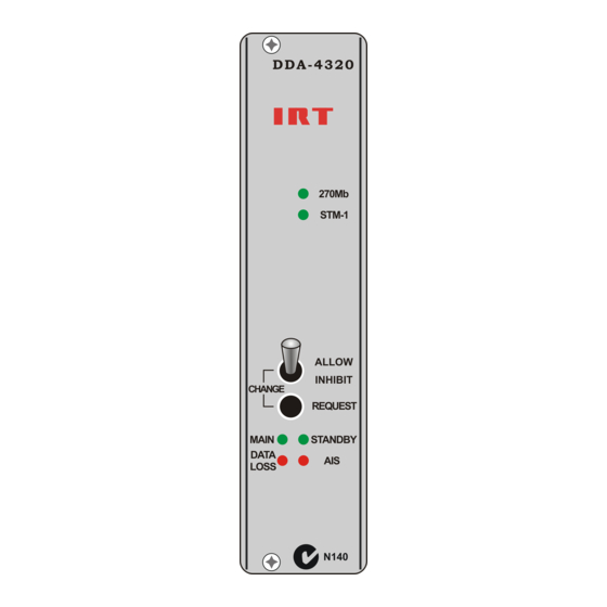
Page 10: Handshaking Operation
Two front panel changeover switches allow manual switching between Main and Standby modes when operating the DDA-4320 as a pair with the ZDA-4320RH double width rear assembly. To select a module as Main, press the Change-Request pushbutton of this module. The Change-Allow/Inhibit switch must be set to the Allow position for the Change-Request button to work. - Page 11 Alarm on loss of input, input signal invalid, AIS detected, or loss of power. Alarm on loss of power. Ground. ZDA-4320RH - Double width rear assembly for switching between two DDA-4320’s. Tally B - unit B is Main. Tally A – unit A is Main.
- Page 12 IRT Electronics modules, fitted with SNMP capability, use SNMPv1. An SNMP managed network consists of three key components: Network Management Systems (NMS), agents, and managed devices.
- Page 13 Communication between the NMS, the frame and its loaded modules are via this CDM-xxxx module. Note that the NMS software is third party and not supplied by IRT Electronics. Ethernet connection for SNMP operation is via an RJ45 connector on the rear of the frame, below the mains inlet.
-
Page 14: Dda-4320 Snmp Functions
Revision 7 DDA-4320 SNMP Functions: With the DDA-4320 installed in an IRT frame fitted with SNMP capability, the following SNMP functions can be monitored and controlled by an SNMP Network Management System (NMS), (Requires MIB revision > 4.4): - Read the status of the Urgent and Non-Urgent alarms: Irt4320ddaAlarms (1) noAlarm. - Page 15 DDA-4320 & ZDA-4320RH Instruction Book Revision 7 - Set whether a Trap is sent on change of operational status, that is Main ↔ Standby: irt4320ddaModuleStatusTrapEn (1) disabled: Trap not sent on change of module state. (2) enabled: Trap sent on change of module state.
-
Page 16: Maintenance & Storage
For situations when “No Fault Found” for repairs, a minimum charge of 1 hour’s labour, at IRT’s current labour charge rate, will apply, whether the equipment is within the warranty period or not.
Need help?
Do you have a question about the DDA-4320 and is the answer not in the manual?
Questions and answers