Table of Contents
Advertisement
Quick Links
© 2006 Global VR. Inc. GLOBAL VR and the GLOBAL VR logo are registered trademarks of Global VR, Inc.
ALIENS ™ & © 1986, 2006 Twentieth Century Fox Film Corporation. All Rights Reserved. Aliens: Extermination, 20th Century Fox and their respective logos are
trademarks of Twentieth Century Fox Film Corporation. Game engine and certain software elements © 2006 Play Mechanix, Inc. Play Mechanix, Inc. and the
Play Mechanix, Inc. logo are trademarks or registered trademarks of Play Mechanix, Inc. All Rights Reserved.
All other trademarks are the properties of their respective owners.
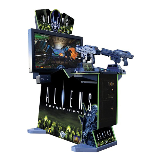
Aliens™ Extermination
System Manual
040-0120-01 Rev. B
Read this manual before use.
Keep this manual with the machine at all times.
www.globalvr.com
http://service.globalvr.com
techsupport@globalvr.com
Phone: 408.597.3435
Fax: 408.597.3437
Advertisement
Table of Contents
Troubleshooting

Related Manuals for Global VR Aliens Extermination


Summary of Contents for Global VR Aliens Extermination
- Page 1 Fax: 408.597.3437 © 2006 Global VR. Inc. GLOBAL VR and the GLOBAL VR logo are registered trademarks of Global VR, Inc. ALIENS ™ & © 1986, 2006 Twentieth Century Fox Film Corporation. All Rights Reserved. Aliens: Extermination, 20th Century Fox and their respective logos are trademarks of Twentieth Century Fox Film Corporation.
-
Page 2: Table Of Contents
Preface Table of Contents Opening the Gun Case........24 Preface ..............4 Closing the Gun Case ........24 Safety..............4 Gun Trigger Service ........25 Warnings ............4 Gun Button Service ........25 Environmental Conditions ......4 Gun Coil Assembly Service ......26 FCC Notices (United States) ......5 Gun Pot and Gear Service ...... - Page 3 Switch ............26 Figure 37. Power Distribution Diagram ....52 Figure 20. Gun Coil Assembly Service .... 26 Figure 38. Computer Rear Panel Diagram ..53 Figure 21. Gun Pot Replacement...... 27 ©2006 Global VR, Inc. 040-0120-01 Rev. B 10/10/2006 Page 3 of 56...
-
Page 4: Preface
To avoid electrical shock, unplug the cabinet before performing installation or service procedures. GLOBAL VR assumes no liability for any damages or injuries incurred while setting up or servicing the cabinet. Only qualified service personnel should perform installation or service procedures! Environmental Conditions Cabinet is intended for indoor use only. -
Page 5: Fcc Notices (United States)
Operation is subject to the following conditions: • This device may not cause harmful interference. • This device must accept any interference received, including interference that may cause undesired operation. ©2006 Global VR, Inc. 040-0120-01 Rev. B 10/10/2006 Page 5 of 56... -
Page 6: Chapter 1 - Introduction
M41-A Pulse Rifle, Flamethrower, Grenades, and Missile Launcher • Power-Up for Health, Ammo, Grenades, Missiles, and Flame Canisters • 4 Levels of Nail Biting Action • Two Different Play Modes – Story and Chapter Aliens Extermination System Manual Page 6 of 56 040-0120-01 Rev. B 10/10/2006... -
Page 7: Cabinet Specifications
Mounted guns with force-feedback recoil • 512 megabytes RAM action and LED ammo readout • 27-inch, 800 x 600, Super VGA • USB Gun interface flat-screen monitor • Supports dollar bill validator ©2006 Global VR, Inc. 040-0120-01 Rev. B 10/10/2006 Page 7 of 56... -
Page 8: Chapter 2 - Installing A New Cabinet
5. Play a game to verify everything is working properly. 6. Refer to Chapter 4 for information on using the Operator menus to set up your game. Figure 3. Back of the Marquee Front Aliens Extermination System Manual Page 8 of 56 040-0120-01 Rev. B 10/10/2006... -
Page 9: Chapter 3 - Playing A Game
6. When your game is about to end, a countdown appears onscreen. To continue, insert coins and press the START button on your side. Figure 4. Using the Guns ©2006 Global VR, Inc. 040-0120-01 Rev. B 10/10/2006 Page 9 of 56... -
Page 10: Chapter 4 - Operator Menu And Game Setup
SELECT. (Pressing the TEST/BACK button to automatically highlight this item.) 6. Once you get back to the Main Menu, highlight EXIT TO GAME and press SELECT to return to the Attract Mode. Figure 5. Operator Buttons Aliens Extermination System Manual Page 10 of 56 040-0120-01 Rev. B 10/10/2006... -
Page 11: Main Menu
Opens Reset Menu where you can clear credits, audits, and adjustments, or RESET MENU return the game to factory default settings. EXIT TO GAME Returns you to the Attract Mode. ©2006 Global VR, Inc. 040-0120-01 Rev. B 10/10/2006 Page 11 of 56... -
Page 12: System Tests Menu
The remaining items each play a tone at the stated frequency, to test the speaker frequency response. BACK TO MAIN MENU Returns you to the Main Menu. Aliens Extermination System Manual Page 12 of 56 040-0120-01 Rev. B 10/10/2006... -
Page 13: Using The Gun Test & Calibrate Screens
9. When finished testing guns, press the SELECT button to return to the System Tests Menu. Figure 8. Gun Calibration Screens ©2006 Global VR, Inc. 040-0120-01 Rev. B 10/10/2006 Page 13 of 56... -
Page 14: Coinage Audits Menu
UNSPENT CREDITS Displays credits currently available. LIFETIME COIN COUNT Displays total credits inserted since the software was installed. BACK TO MAIN MENU Returns you to the Main Menu. Aliens Extermination System Manual Page 14 of 56 040-0120-01 Rev. B 10/10/2006... -
Page 15: System Audits Menu
Displays the number of times a game has been started for Player 1. PLAYER 2 STARTS Displays the number of times a game has been started for Player 2. BACK TO MAIN MENU Returns you to the Main Menu. ©2006 Global VR, Inc. 040-0120-01 Rev. B 10/10/2006 Page 15 of 56... -
Page 16: Game Audits Menu
MISC AUDITS Displays additional detailed game play statistics. BACK TO MAIN MENU Returns you to the Main Menu. Aliens Extermination System Manual Page 16 of 56 040-0120-01 Rev. B 10/10/2006... -
Page 17: Coinage Adjustments Menu
INSERT COIN MESSAGE Sets the payment message displayed in Attract Mode. (Options: Insert Coins, Insert Card, Insert Key, Swipe Card) BACK TO MAIN MENU Returns you to the Main Menu. ©2006 Global VR, Inc. 040-0120-01 Rev. B 10/10/2006 Page 17 of 56... -
Page 18: System Adjustments Menu
Sets whether the Attract Mode plays sound effects (Alien scream, etc.) Options are ON, OCCASIONALLY, or OFF. GAMMA Increases or decreases the overall screen brightness. BACK TO MAIN MENU Returns you to the Main Menu. Aliens Extermination System Manual Page 18 of 56 040-0120-01 Rev. B 10/10/2006... -
Page 19: Game Adjustments Menu
LITE plays in Story Mode only, and omits the two levels that are the most violent. (Default: FULL) BACK TO MAIN MENU Returns you to the Main Menu. ©2006 Global VR, Inc. 040-0120-01 Rev. B 10/10/2006 Page 19 of 56... -
Page 20: Gun Adjustments Menu
Higher numbers make the recoil stronger; lower P2 GUN POWER numbers make the recoil weaker. (Options: 25%-133%; Default: 100%) BACK TO MAIN MENU Returns you to the Main Menu. Aliens Extermination System Manual Page 20 of 56 040-0120-01 Rev. B 10/10/2006... -
Page 21: Reset Menu
Returns all adjustments to default values. FACTORY RESET Returns all settings to factory default values. Does not affect audits. BACK TO MAIN MENU Returns you to the Main Menu. ©2006 Global VR, Inc. 040-0120-01 Rev. B 10/10/2006 Page 21 of 56... -
Page 22: Chapter 5 - Software Restoration
3. When the computer reboots, you will see a series of processing screens. After about 3 minutes the computer will automatically reboot. You will briefly see a message to insert Game Disk 1, followed by the GLOBAL VR logo on the screen. Proceed to install the Game Install CD as described below. -
Page 23: Chapter 6 - Service And Repair
Chapter 6 — Service and Repair Chapter 6 — Service and Repair CAUTION: GLOBAL VR assumes no liability for any damage or injuries incurred while servicing the cabinet. Only qualified service personnel should perform service and installation of cabinet hardware. -
Page 24: Opening The Gun Case
The screw at the top of the muzzle end is 3/4" long, and the two screws in the handle are 1" long, as shown above. All of the other screws are 1 ¼" long. Aliens Extermination System Manual Page 24 of 56... -
Page 25: Gun Trigger Service
To replace the light bulb, pull the lamp assembly straight out of the button housing, and then pull the bulb straight out of the lamp housing. The two lamp wires are interchangeable and can connect to either terminal on the lamp housing. ©2006 Global VR, Inc. 040-0120-01 Rev. B 10/10/2006 Page 25 of 56... -
Page 26: Gun Coil Assembly Service
Figure 20. Gun Coil Assembly Service 5. Reverse these steps to re-install the coin assembly. Be sure to secure the ground wire to the ground lug on the coil assembly mounting plate. Aliens Extermination System Manual Page 26 of 56 040-0120-01 Rev. B 10/10/2006... -
Page 27: Gun Pot And Gear Service
8. Re-install the gear shaft and tighten the set screw. 9. Calibrate the gun using the Gun Test & Calibrate screen from System Tests in the Operator menu after replacing a pot. Figure 21. Gun Pot Replacement ©2006 Global VR, Inc. 040-0120-01 Rev. B 10/10/2006 Page 27 of 56... -
Page 28: The Gun Pcb
Caution: Disconnect the cabinet from AC power before making any connections to the Gun PCB. Hot-plugging any connector will damage the PCB. Figure 22. Gun PCB Figure 23. Gun Internal Parts Aliens Extermination System Manual Page 28 of 56 040-0120-01 Rev. B 10/10/2006... -
Page 29: Gvri/O Pcb Service
4. To remove the lamp housing, gently rock the white plastic housing from side to side to pop it out of the button housing. ©2006 Global VR, Inc. 040-0120-01 Rev. B 10/10/2006 Page 29 of 56... -
Page 30: Wells-Gardner Monitor Replacement
5. Remove the retaining brackets from above and below the monitor. The upper bracket is secured with three Torx security screws, the lower bracket with four screws (two near each end). Aliens Extermination System Manual Page 30 of 56 040-0120-01 Rev. B 10/10/2006... -
Page 31: Wells-Gardner Monitor Chassis Pcb Removal
You can replace the monitor chassis PCB if you have problems with just the PCB. Caution: Only a certified technician should attempt to remove or service the Monitor PCB. GLOBAL VR assumes no responsibility for damage while removing the PCB. -
Page 32: Figure 26. Removing The Monitor Pcb Mounting Hardware
Disconnect the CRT 2-wire ground cable that connects to the Chassis Monitor PCB (Item 1 in Figure 28). b. Disconnect the CRT 2-wire ground cable that connects to the Chassis Neck PCB (Item 2 in Figure 28). Aliens Extermination System Manual Page 32 of 56 040-0120-01 Rev. B 10/10/2006... -
Page 33: Computer Replacement
There is an air vent under the bottom front panel of the computer that is easily blocked by padding or debris. When shipping the computer, always use plenty of padding and protection. GLOBAL VR recommends shipping the computer in a box with three inches of foam padding on all sides. -
Page 34: Coin Mech Replacement
AC power from the power plate is connected to a 7-outlet AC power strip/surge suppressor in the cabinet. Caution: The cabinet must be connected to a secure ground to function properly. Aliens Extermination System Manual Page 34 of 56 040-0120-01 Rev. B 10/10/2006... -
Page 35: Ac Power Strip Replacement
4. Remove the power strip; it is held in place with Velcro 5. Replace the power strip with an appropriate unit from GLOBAL VR (part # 49-0963-40). Do not attempt to use a different power strip. Be sure to connect each wire to the correct terminal (See Power Distribution Diagram on page 52.) -
Page 36: Marquee Florescent Light Service
2-Pin Connector Attached to Tube Cold-Cathode Florescent Tubes +12 VDC In from DC Power Supply Power Inverter Figure 31. Cold-Cathode Light Detail Aliens Extermination System Manual Page 36 of 56 040-0120-01 Rev. B 10/10/2006... -
Page 37: Setting The Computer Bios (Cmos)
(↑↓) to select the CD-ROM drive, and press Enter. The hard drive will automatically be set as the 2 Boot Device. Press the Esc key to exit from the submenu. ©2006 Global VR, Inc. 040-0120-01 Rev. B 10/10/2006 Page 37 of 56... - Page 38 11. Now that all settings are correct, press F10. The following prompt will appear: Save configuration changes and exit now? [Ok] [Cancel] 12. Make sure Ok is selected (use the arrow keys to select if necessary) and press Enter. Aliens Extermination System Manual Page 38 of 56 040-0120-01 Rev. B 10/10/2006...
-
Page 39: Chapter 7 - Replacement Parts
Chapter 7 — Replacement Parts Chapter 7 — Replacement Parts If you need replacement parts, please reference these part numbers when contacting GLOBAL VR technical support or your distributor. Documents and Software Part Number Item Description 040-0120-01 System Manual 040-0121-01... - Page 40 Also see pages 42 and 43. Part Number Qty per Gun Item Description 26090-01 Gun Housing, Left 26090-02 Gun Housing, Right 96-0799-00 Gun Assembly METL6R LED Light Tube, Red 990-0012-01 Gun PCB Aliens Extermination System Manual Page 40 of 56 040-0120-01 Rev. B 10/10/2006...
-
Page 41: Figure 32. Cabinet Artwork
Chapter 7 — Replacement Parts Cabinet Artwork Figure 32. Cabinet Artwork ©2006 Global VR, Inc. 040-0120-01 Rev. B 10/10/2006 Page 41 of 56... - Page 42 SCREW 8-32 X 1/4"BUTTON HD TORX TAMP BLK OX. 43-0211-00 NUT, 8-32 NYLOK 43-2318-00 SCREW 8-32 X 5/8 BHMS TORX 43-2317-00 SCREW 8-32 X 7/8 BHMS TORX 43-0172 00 SCREW, #2 X 1/2 TYPE B. PPH Aliens Extermination System Manual Page 42 of 56 040-0120-01 Rev. B 10/10/2006...
-
Page 43: Figure 33. Gun Exploded-View Drawing
Chapter 7 — Replacement Parts Figure 33. Gun Exploded-View Drawing ©2006 Global VR, Inc. 040-0120-01 Rev. B 10/10/2006 Page 43 of 56... -
Page 44: Chapter 8 - Troubleshooting
Use the Screen Size Adjustment screen from Video Screen Tests in System Tests in the Operator Menu to aid with adjustments. Aliens Extermination System Manual Page 44 of 56 040-0120-01 Rev. B 10/10/2006... -
Page 45: Audio Troubleshooting
This could be either the external DC power supply or the computer power supply. Open ground Check all ground wires in the cabinet. Make sure AC wall outlet is properly grounded. ©2006 Global VR, Inc. 040-0120-01 Rev. B 10/10/2006 Page 45 of 56... -
Page 46: Button Troubleshooting
A button or trigger Faulty micro switch Check micro switch inside gun. Check wiring. Make sure does not work or wiring no wires are pinched in the gun case. Aliens Extermination System Manual Page 46 of 56 040-0120-01 Rev. B 10/10/2006... -
Page 47: Miscellaneous Troubleshooting
AC outlet, and the cabinet ON/OFF switch is ON. Blown fuse in power Check the fuses in the power entry module in the power plate plate. ©2006 Global VR, Inc. 040-0120-01 Rev. B 10/10/2006 Page 47 of 56... - Page 48 Repair or replace if faulty. Coin meter does not Blown fuse(s) on Replace the 5 Amp fuse(s) on the GVRI/O PCB. work GVRI/O PCB Aliens Extermination System Manual Page 48 of 56 040-0120-01 Rev. B 10/10/2006...
-
Page 49: Chapter 9 - Diagrams And Schematics
VOL UP VOL UP Button WHT/GRN Operator Panel Buttons NOTES: Wire colors may vary due to harness revisions. Unused pins are not shown. Figure 34. GVRI/O Wiring Diagram ©2006 Global VR, Inc. 040-0120-01 Rev. B 10/10/2006 Page 49 of 56... -
Page 50: Figure 35. Gun Wiring Diagram
Chapter 9 — Diagrams and Schematics Caution: Disconnect power before changing any USB connections or you will damage the PCBs. Figure 35. Gun Wiring Diagram Aliens Extermination System Manual Page 50 of 56 040-0120-01 Rev. B 10/10/2006... -
Page 51: Figure 36. Overall Cabinet Wiring Diagram
Chapter 9 — Diagrams and Schematics Figure 36. Overall Cabinet Wiring Diagram ©2006 Global VR, Inc. 040-0120-01 Rev. B 10/10/2006 Page 51 of 56... -
Page 52: Figure 37. Power Distribution Diagram
To Cabinet Ventillation Fan +24V (White) +12V (Yellow) Part #: 115-0097-01* Part #: 115-0101-01 *Power Harness contains two fuses, one for each gun. Figure 37. Power Distribution Diagram Aliens Extermination System Manual Page 52 of 56 040-0120-01 Rev. B 10/10/2006... -
Page 53: Figure 38. Computer Rear Panel Diagram
Port 1: Open, Port 2: GVRI/O PCB, Port 3: Left Gun (Marine 1), Port 4: Right Gun (Marine 2) Game Dongle GVRI/O PCB Motherboard USB Port Connection Details: Left Gun Right Gun (Marine 1) (Marine 2) Figure 38. Computer Rear Panel Diagram ©2006 Global VR, Inc. 040-0120-01 Rev. B 10/10/2006 Page 53 of 56... -
Page 54: Warranty Information
Purchaser. GLOBAL VR is not obligated to provide the Purchaser with a ® substitute unit or on-site service during the warranty period or at any time. If after investigation GLOBAL VR determines that the reported problem ®... -
Page 56: Technical Support
Saturday & Sunday 7:00am—Midnight Pacific Time Free telephone, e-mail, and online support are provided for systems during the warranty period. GLOBAL VR Technical Support can help you troubleshoot problems and diagnose defective parts. We can also answer questions about the operation of your game.
Need help?
Do you have a question about the Aliens Extermination and is the answer not in the manual?
Questions and answers