Table of Contents
Advertisement
Available languages
Available languages
Quick Links
ATTACH YOUR RECEIPT HERE AND REGISTER YOUR FAN AT FANIMATION.COM
READ AND SAVE THESE INSTRUCTIONS
Serial Number
Questions, problems, missing parts? Before returning to your retailer, call our customer
service department at 1-888-567-2055, 8 a.m.-5 p.m., EST, Monday-Friday.
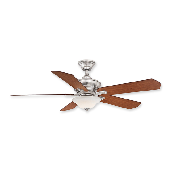
CAMHAVEN v2 CEILING FAN
Purchase Date
™
MODEL #FP8094**
Español p. 22
Net Weight 21.38 lbs (9.7 kg)
Advertisement
Chapters
Table of Contents

Related Manuals for Fanimation CAMHAVEN FP8094 Series


Summary of Contents for Fanimation CAMHAVEN FP8094 Series
-
Page 1: A E S M I L B G N F N A W T I T H E H L G I T H K . T
CAMHAVEN v2 CEILING FAN ™ MODEL #FP8094** Español p. 22 ATTACH YOUR RECEIPT HERE AND REGISTER YOUR FAN AT FANIMATION.COM READ AND SAVE THESE INSTRUCTIONS Serial Number Purchase Date Net Weight 21.38 lbs (9.7 kg) Questions, problems, missing parts? Before returning to your retailer, call our customer... - Page 2 Fanimation. 7. Fanimation reserves the right to modify or discontinue any product at any time and may substitute any part under this warranty. 8. Under no circumstances may a fan be returned without prior authorization from Fanimation. The receipt of purchase must ac- company authorized returns and must be sent freight prepaid to Fanimation.
-
Page 3: Table Of Contents
Table of Contents Unpacking Instructions i l b . t i Energy Effi cient Use of Ceiling Fans......5 Assembling Fan Without the Light Kit . -
Page 4: Unpacking Instructions
– 1/4 -20 Pan Head Screw • Blade Holder Set Fanimation. Substitution of parts or accessories not (blade arm to motor) designated for use with this product by Fanimation could • Blade Set – Wire Connectors result in personal injury or property damage. Contact •... -
Page 5: Energy Efficient Use Of Ceiling Fans
8 - 9 feet from floor to the blade for optimal down into the occupied space.Remember to adjust your airflow. Consult your Fanimation Retailer for optional thermostat when using your ceiling fan - additional energy and dollar savings could be realized with this simple step! mounting accessories. - Page 6 Electrical and Structural Requirements (Continued) Deep box with brace (Figure 3) Paired with a deep box, this hanger is meant to span CEILING JOIST between two joists and takes the place of wooden blocking. WARNING To reduce the risk of fire, electric shock, or personal injury, mount to outlet box marked acceptable for fan support of 15.9 kg (35 lbs) or less and use mounting screws provided with the outlet box.
-
Page 7: How To Assemble Your Ceiling Fan
How to Assemble Your Ceiling Fan Remove the hanger ball portion from the downrod /hanger ball assembly by loosening the set screw in the hanger ball until the ball falls freely down the Downrod downrod. Remove the pin from the downrod, then Hanger remove the hanger ball. - Page 8 How to Assemble Your Ceiling Fan (continued) Route wires through motor coupling cover, canopy screw cover and ceiling canopy. (Figure 5) Ceiling Canopy Canopy Screw Motor Cover Coupling Cover Figure 5 Reinstall the hanger ball on the downrod as follows. Route the three wires through the hanger ball.
-
Page 9: How To Hang Your Ceiling Fan
How to Hang Your Ceiling Fan WARNING To avoid possible electrical shock, be sure electricity is turned off at the main fuse box before hanging. (Figure 1) NOTE: If you are not sure if the outlet box is grounded, contact a licensed electrician for advice, as it must be grounded for safe operation. -
Page 10: How To Wire Your Ceiling Fan
How to Wire Your Ceiling Fan 1. To set the code on receiver unit, slide dip switches to Receiver Unit the same positions as set on the remote. (Figure 1) NOTE: The remote unit has 32 different code combinations. To prevent possible interference from or to other remote units, simply change the combination code Dip Switch in the remote and receiver. -
Page 11: Installing The Canopy Housing
Installing the Canopy Housing NOTE: This step is applicable after the necessary wiring is completed. ▲WARNING To avoid possible fire or shock, make sure that the electrical wires are completely inside the canopy housing and not pinched between the housing and the ceiling. 1. -
Page 12: Assembling And Mounting The Fan Blades
Assembling and Mounting the Fan Blades 1. Position the blade over the blade holder with threaded posts showing. Make sure the bottom edge of the blade is fully seated against the blade arm. With a phillips screwdriver, tighten Blade Holder Arm 3/16 -24 washer head screws and fiber washers to secure the blade to the blade arm. - Page 13 Assembling Fan With the Light Kit If you are assembling your fan without the light kit, please skip to page 15 of this manual. NOTE: CAUTION Switch cup support plate To reduce the risk of electric shock, disconnect the electrical supply circuit to the fan before installing light kit.
- Page 14 Assembling Fan With the Light Kit (continued) c t i the assembled switch cup support plate with three screws. (Figure 5) Figure 5 6. Secure glass bowl to light fitter using supplied nut. Next, install trim cover followed by the finial. Do not over tighten.
-
Page 15: Assembling Fan Without The Light Kit
Assembling Fan Without the Light Kit 1. Disassemble the adapter/switch cup assembly from Switch cup support the switch cup support plate by removing three plate screws. (Figure 1) Adapter/Switch cup assembly Figure 1 2. Remove one of the three screws in the support bracket at the bottom of the motor assembly. -
Page 16: How To Operate Your Ceiling Fan
How to Operate Your Ceiling Fan IMPORTANT: Using a full range dimmer switch (not included) to control fan speed will damage the fan. To reduce the risk of fire or electrical shock, do not use a full range dimmer switch to control the fan speed. (Figure 1) Restore electrical power to the outlet box by turning the electricity on at the main fuse box. -
Page 17: How To Install Your Remote Control
How to Operate Your Ceiling Fan (continued) 6. If airflow is desired in the opposite direction, turn the fan off and wait for the blades to stop turning. Then slide the reverse switch on top of motor Reverse assembly to the opposite position and turn fan on Switch again. -
Page 18: Parts List
Parts List Model #FP8094** Ref.# Description Part # Ceiling Canopy P809501** Blade Set Blade Holder Set Glass Bowl P809404FW 06005000 Hand Held Remote TR500 Hardware Bag Containing: Blade Mounting Hardware Bag Containing: 3/16 Blade Holder Mounting Hardware Bag Containing: Refer to fan model number located on down rod support Before discarding packaging materials, be certain all parts have been removed How To Order Parts When ordering repair parts, always... -
Page 19: Exploded-View Illustration
The Camhaven v2- FP8094** ™ Exploded-View Illustration Figure 1 NOTE: u l l s t i... -
Page 20: Troubleshooting
Troubleshooting ▲WARNING For your own safety turn off power at fuse box or circuit breaker before trouble shooting your fan. Trouble Probable Cause Suggested Remedy 1. FAN WILL NOT START 1. Fuse or circuit breaker blown. 1. Check main and branch circuit fuses or circuit breakers. - Page 21 10983 Bennett Parkway Zionsville, IN 46077 Phone: 888-567-2055 Outside U.S.: 317-733-4113 2019/01 V.01 FAX: 866-482-5215 Copyright 2019 Fanimation FANIMATION.COM...
- Page 22 VENTILADOR DE TECHO CAMHAVEN v2 ™ MODELO #FP 8094** ADJUNTE SU RECIBO AQUÍ Y REGISTRE SU VENTILADOR EN FANIMATION.COM LEA Y GUARDE ESTAS INSTRUCCIONES Número de serie Peso neto 9.7 kg (21.38 lbs) Fecha de compra Preguntas, problemas, piezas faltantes? Antes de volver a la tienda, llame a nuestro Departamento de Servicio al Cliente al 1-888-567-2055, 8 a.m.
- Page 23 GARANTÍA LIMITADA DE POR VIDA DEL MOTOR - Si se produjera una falla en alguna de las partes del motor de su ventilador debido a un defecto en los materiales o en la fabricación durante el tiempo de vida del comprador original, Fanimation proporcionará la pieza de repuesto sin cargo una vez que el ventilador defectuoso sea devuelto a nuestro centro de servicios nacional.
- Page 24 En ningún caso se podrá devolver un ventilador sin previa autorización por parte de Fanimation. Las devoluciones autorizadas deberán ir acompañadas del recibo de venta y deberán enviarse a Fanimation, previo pago del flete. El ventilador que se devuelva deberá estar embalado en forma adecuada a fin de evitar daños durante el transporte. Fanimation no se hará responsable de los daños que resulten del embalaje incorrecto del producto.
-
Page 25: Instrucciones Para El Desempaque
Fanimation específicamente pag-nant et/ou les accessoires spécifiquement conçus para el mismo. La sustitución de piezas o accesorios no pour ce produit par Fanimation. La substitution de designados por Fanimation para usar con este producto pièces ou d'accessoires non conçus par Fanimation podría ocasionar lesiones personales o daños en el... -
Page 26: Requisitos Eléctricos Y Estructurales
óptimo. Consulte en que obliga al aire cálido que se acumula cerca del techo a su tienda minorista de Fanimation para obtener bajar al espacio ocupado. No olvide ajustar el termostato accesorios de montaje opcionales. - Page 27 Requisitos eléctricos y estructurales (cont.) Uso del soporte (Figura 3) Conectado a una caja de distribución eléctrica, este colgador Vigas del techo sirve para abarcar el espacio entre dos vigas y ocupar el lugar de bloqueo de la madera. ADVERTENCIA Para reducir el riesgo de incendios, descargas eléctricas o lesiones personales, fije el ventilador a la caja de distribución eléctrica marcada como aceptable para...
-
Page 28: Cómo Ensamblar El Ventilador De Techo
Cómo ensamblar el ventilador de techo 1. Extraiga la pieza de la bola colgante de la unidad de la bola colgante / varilla aflojando el tornillo de presión de la bola colgante hasta que la bola se Varilla libere de la varilla. Retire el pasador del barral y Pasador Ranura de la luego extraiga la semiesfera. - Page 29 Cómo ensamblar el ventilador de techo (cont.) Capuchón de techo la cubierta del Cubierta de tornillo de la base unión del motor Figura 5 Vuelva a colocar la semiesfera en el barral como se indica a continuación. Pase los tres cables de alinee la semiesfera de modo que el pasador quede atrapado en la ranura de la parte superior de la misma.
-
Page 30: Cómo Colgar El Ventilador De Techo
Cómo colgar el ventilador de techo ADVERTENCIA Para evitar una posible descarga eléctrica, asegúrese de cortar la alimentación eléctrica de la caja de fusiblesprincipal antes de colgar el ventilador. (Figura 1) PRINCIPAL CAJA DE FUSIBLES NOTA: Si no está seguro de si la caja de salida tiene conexión a tierra, pida consejo a un electricista certificado, ya que debe tener conexión a tierra para un funcionamiento seguro. - Page 31 Cómo colgar el ventilador de techo (cont.) 4. Levante cuidadosamente el ventilador y coloque el ensamble de la bola para colgar/varilla en la abrazadera para colgar que acaba de fijar a la caja de salida. Asegúrese de que la ranura de la bola esté alineada con la lengüeta de la abrazadera para colgar.
-
Page 32: Cómo Realizar La Instalación Eléctrica Del Ventilador De Techo
Cómo realizar la instalación eléctrica del ventilador de techo NOTA: El mando a distancia incluido en este ventilador Unidad del receptor tiene 32 combinaciones diferentes de códigos. Para evitar posibles interferencias desde o hacia otros mandos a distancia, modifique el código de combinación de su transmisor y receptor. -
Page 33: Instalación De La Cubierta Del Capuchón
Cómo realizar la instalación eléctrica del ventilador de techo (cont.) 3. Una vez realizadas las conexiones, gire los Conductor blanco Conductor verde conductores hacia arriba y, con cuidado, colóquelos del suministro Caja de salida (puesta a tierra) dentro de la caja de salida; con los conductores blancos y homologada verdes hacia un lado y los conductores negros hacia el Suministro... -
Page 34: Ensamblaje De Las Aspas Del Ventilador
Ensamblaje de las aspas del ventilador 1. Coloque el aspa sobre el soporte de aspas con los pilotes roscados a la vista. Asegúrese de que la parte inferior del aspa se encuentre bien apoyada sobre el soporte. Con un destornillador Phillips, fije Soporte de aspas para asegurar la placa en el brazo de sujeción de las palas. -
Page 35: Montaje Del Ventilador Con El Kit De Iluminación
Montaje del ventilador con el kit de iluminación Si está realizando el montaje de su ventilador sin el kit de iluminación, vaya directamente a la página 35 NOTA: de este manual. PRECAUCIÓN Cubierta del interruptor placa de soporte A fin de reducir el riesgo descargas eléctricas, desconecte el circuito de suministro eléctrico al ventilador antes de instalar el kit de iluminación. - Page 36 Montaje del ventilador con el kit de iluminación (cont.) 5. Instale el soporte del interruptor de la carcasa en el adaptador ensamblado mediante los tres tornillos. (Figure 5) Figura 5 6. Asegure la carcasa de vidrio en la unidad del kit de iluminación utilizando la tuerca suministrada.
-
Page 37: Montaje Del Ventilador Sin El Kit De Iluminación
Montaje del ventilador sin el kit de iluminación Desmonte la unidad del adaptador / cubierta del Cubierta del interruptor interruptor desde el cubierta del interruptor placa de placa de soporte soporte extrayendo los tres tornillos. (Figura 1) Unidad del adaptador / cubierta del interruptor Figura 1 2. -
Page 38: Cómo Utilizar Su Ventilador De Techo
Cómo utilizar su ventilador de techo El uso de un regulador de la intensidad completa (no incluido) para controlar la velocidad del ventilador dañará el dispositivo. Para reducir el riesgo de incendio o descarga eléctrica, no utilice dicho regulador para controlar la velocidad del ventilador. -
Page 39: Cómo Instalar Su Mando A Distancia
Cómo utilizar su ventilador de techo (cont.) 5. Funciones del control remoto: (Figura 5) Luz LED del indicador: Velocidad del ventilador Enciende el ventilador y aumenta la velocidad. Enciende el ventilador y disminuye la velocidad. Enciende el ventilador y aumenta la velocidad. Figura 5 Temporizador de apagado automático: Pulse y tanto el ventilador y la iluminación se... -
Page 40: Limpieza De Las Aspas
Mantenimiento PRECAUCIÓN El único mantenimiento necesario para el ventilador de techo es una limpieza periódica. Al llevar a cabo la limpieza, use sólo un cepillo suave o un No utilice solventes para limpiar el ventilador de techo. Podrían dañar el motor o las aspas y ocasionar posibles paño sin pelusas, para evitar rayar el acabado. -
Page 41: Lista De Piezas
Lista de piezas Modelos N.° FP8094** N.° de Ref. Descripción Pieza # N.° Unidad del soporte de suspensión AP255BL Unidad del barral/de la semiesfer P809501** AP260** AP809502** AMA8094** Juego de aspas AP809405** Juego de soporte de Aspas AP809413** Unidad del adaptador / cubierta del interruptor AP809506** Mando a distancia 06005000... -
Page 42: Ilustración Del Despiece
The Camhaven v2- FP8094** ™ Ilustración del despiece Figura 1 NOTA: la ilustración que se muestra no está hecha a... -
Page 43: Solución De Problemas
Solución de problemas ▲ ADVERTENCIA Para su propia seguridad, desconecte la electricidad de la caja de fusibles o disyuntor antes de solucionar problemas en su ventilador. ▲AVERTISSEMENT Pour votre sécurité, placez le coffret à fusibles ou le disjoncteur hors tension avant de tenter d’identifier tout problème pouvant affecter votre ventilateur. - Page 44 10983 Bennett Parkway Zionsville, IN 46077 Phone: 888-567-2055 Outside U.S.: 317-733-4113 2019/01 V.01 FAX: 866-482-5215 Copyright 2019 Fanimation FANIMATION.COM...
Need help?
Do you have a question about the CAMHAVEN FP8094 Series and is the answer not in the manual?
Questions and answers