Table of Contents
Advertisement
Advertisement
Table of Contents

Related Manuals for krom schroeder MPT 700


Summary of Contents for krom schroeder MPT 700
- Page 1 Impulse system MPT 700 Manual 6.2.2.2 Edition 1.03 GB...
-
Page 2: Table Of Contents
MPT 700 1 Introduction ..................4 Version and model ..................... 5 CE Mark......................7 2 Operation ................... 8 Controls ......................8 2.1.1 Front panel....................8 2.1.2 Parameter display ..................9 2.1.3 Group indicator .................... 9 2.1.4 Setting source indicators................9 2.1.5... - Page 3 MPT 700 4.18 Parameters 50...53 / 56...59 / 70...73 / 76...79 - delays ........ 39 4.19 Parameter 87 - equipment code..............40 5 Appendix..................41 Installation ......................41 5.1.1 Proper use....................41 5.1.2 Installation notes and safety precautions ........... 41 5.1.3...
-
Page 4: Introduction
You have opted for our new generation of equipment in accordance with CE requirements, the MPT 700 Rev.C burner cycle control unit, which is designed for controlling up to eight burners in one or two groups in any of eight modes of operation. -
Page 5: Version And Model
- one three-point step input for multiplex operation The MPT 700 can be adjusted to behave in the same way as a single-group unit by setting the number of outputs for group 1 to 8 burners (parameter 15) and for group 2 to 0 burners (parameter 16) and the setting indicator to group 1 (parameter 14). - Page 6 For downward compatibility reasons, it is still possible to operate the MPT 700 in the 608 software mode (see section 4.6) For intention to replace the MPT 608 as well as the MPT 618 with the MPT 700, it's necessaray to make some changes in the wireing of the installation: •...
-
Page 7: Ce Mark
Januar 1997 all temporary regulations had been dropped, so the new "EG concurring standartisations" are valid. The MPT 700 burner cycle control unit described in this manual is supplied complete with a CE mark guaranteeing: • compliance with the electromagnetic compatibility directive... -
Page 8: Operation
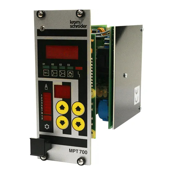
MPT 700 2 Operation 2.1 Controls 2.1.1 Front panel group indicator 4-digit parameter display setting source indicators malfunction indicator 2-digit parameter number display keypad switching output indicators... -
Page 9: Parameter Display
1 ⇒ 2 bars group 2 2.1.4 Setting source indicators • These indicators show the setting source which is currently active. ⇒ MPT 700: no function ⇒ control by analogue 0/4...20mA signal ⇒ three-point step controller ⇒ manual control •... -
Page 10: Malfunction Indicator
MPT 700 2.1.5 Malfunction indicator ⇒ unit malfunction • If the unit detects a malfunction during its cyclical self-test, the red LED is lit, the 4 green LEDs all flash and the binary "malfunction" output signal is activated. Troubleshooting is described in section 5.4 below. -
Page 11: Operation Of The Unit
This delay prevents uncontrolled changes in parameter selection. Parameter Meaning all outputs are reset MPT 700: no function setting from controller (continuous / three-point step) manual setting for group 1 manual setting for group 2 2.2.3 Parameter entry - general •... - Page 12 MPT 700 2.2.3.1 Selection of parameters • All the parameters can be checked while the unit is in service without any effect on operation. • To check a parameter, select the parameter required using the left half of the keypad.
-
Page 13: Modes Of Operation
MPT 700 3 Modes of operation 3.1 Mode of operation 1 - heating with fixed pulse width • The pulse width is set to a fixed value for each channel. • If the setting is changed, the pulse spacing is changed. -
Page 14: Mode Of Operation 2 - Heating/Cooling With Fixed Pulse Width
MPT 700 3.2 Mode of operation 2 - heating/cooling with fixed pulse width • The pulse width is set to a fixed value for each channel. • If the setting is changed, the pulse spacing is changed. • Max. pulse frequency = 1 / (pulse width + minimum off time) •... - Page 15 MPT 700 Adjustable parameters in mode of operation 2: Parameter Designation Range Section Remarks (G1/G2) setting source 0...5 mode of operation 12/13 equipment address 1...32 not relevant for operation setting indicator 0...2 15/16 number of outputs 0...8 MPT mode 108/128 keyboard repetition rate 1...32...
-
Page 16: Mode Of Operation 3 - Heating With Variable Pulse Width And Spacing
MPT 700 3.3 Mode of operation 3 - heating with variable pulse width and spacing • In this mode of operation, no fixed pulse widths are defined. • The pulse width or the pulse spacing changes as a function of the setting. - Page 17 MPT 700 Adjustable parameters in mode of operation 3: Parameter Designation Range Section Remarks (G1/G2) setting source 0...5 mode of operation 12/13 equipment address 1...32 not relevant for operation setting indicator 0...2 15/16 number of outputs 0...8 MPT mode 108/128 keyboard repetition rate 1...32...
-
Page 18: Mode Of Operation 4 - Heating/Cooling With Variable Pulse Width And Spacing
MPT 700 3.4 Mode of operation 4 - heating/cooling with variable pulse width and spacing • In this mode of operation, no fixed pulse widths are defined. • The pulse width or the pulse spacing changes as a function of the setting. - Page 19 MPT 700 Pulse diagram: 1. setting 1% ⇒ min. on time / max. off time 2. setting 1%...XX% ⇒ min. on time / off time is reduced 3. setting XX% ⇒ min. on time / min. off time maximum pulse frequency 4.
- Page 20 MPT 700 Adjustable parameters in mode of operation 4: Parameter Designation Range Section Remarks (G1/G2) setting source 0...5 mode of operation 12/13 equipment address 1...32 not relevant for operation setting indicator 0...2 15/16 Number of outputs 0...8 MPT mode 108/128 keyboard repetition rate 1...32...
-
Page 21: Mode Of Operation 5 - Heating With Fixed Pulse Width And Separate Air And Gas Valve Control
MPT 700 3.5 Mode of operation 5 - heating with fixed pulse width and separate air and gas valve control • The pulse width is set to a fixed value for each channel. ( air- and gas valve ) The pulse widths for the air valves can be set in parameter 40,42,44,46 and for the gas valves in parameter 41,43,45,47. - Page 22 MPT 700 Adjustable parameters in mode of operation 5: Parameter Designation Range Section Remarks (G1/G2) setting source 0...5 mode of operation 12/13 equipment address 1...32 not relevant for operation setting indicator 0...2 15/16 number of outputs 0...8 MPTde 108/128 keyboard repetition rate 1...32 20,22,24,26 ZZP1, 3, 5, 7 0/1...255...
-
Page 23: Mode Of Operation 6 - Heating/Cooling With Fixed Pulse Width And Separate Air And Gas Valve Control
MPT 700 3.6 Mode of operation 6 - heating/cooling with fixed pulse width and separate air and gas valve control • The pulse width is set to a fixed value for each channel. ( air- and gas valve ) The pulse widths for the air valves can be set in parameter 40,42,44,46 and for the gas valves in parameter 41,43,45,47. - Page 24 MPT 700 Adjustable parameters in mode of operation 6: Parameter Designation Range Section Remarks (G1/G2) setting source 0...5 mode of operation 12/13 equipment address 1...32 not relevant for operation setting indicator 0...2 15/16 number of outputs 0...8 MPT mode 108/128 keyboard repetition rate 1...32...
-
Page 25: Mode Of Operation 7- Heating With Variable Pulse Width And Spacing And Separate Air And Gas Valve Control
MPT 700 3.7 Mode of Operation 7- heating with variable pulse width and spacing and separate air and gas valve control • In this mode of operation, no fixed pulse widths are defined. • The pulse width or the pulse spacing changes as a function of the setting. - Page 26 MPT 700 Pulse diagram: 1. setting 1% ⇒ min. on time / max. off time air valve gas valve delay 2. setting 1%...XX% ⇒ min. on time / off time is reduced air valve gas valve delay 3. setting XX% ⇒...
- Page 27 MPT 700 Adjustable parameters in mode of operation 7: Parameter Designation Range Section Remarks (G1/G2) setting source 0...5 mode of operation 12/13 equipment address 1...32 not relevant for operation setting indicator 0...2 15/16 number of outputs 0...8 MPT mode 108/128 keyboard repetition rate 1...32...
-
Page 28: Mode Of Operation 8 - Heating/Cooling With Variable Pulse Width And Spacing And Separate Air And Gas Valve Control
MPT 700 3.8 Mode of Operation 8 - heating/cooling with variable pulse width and spacing and separate air and gas valve control • In this mode of operation, no fixed pulse widths are defined. • The pulse width or the pulse spacing changes as a function of the setting. - Page 29 MPT 700 Pulse diagram: ⇒ min. on time / max. off time 1. setting 1% air valve gas valve delay ⇒ min. on time / off time is reduced 2. setting 1%...XX% air valve gas valve delay ⇒ min. on time / min. off time maximum pulse 3.
- Page 30 MPT 700 Adjustable parameters in mode of operation 8: Parameter Designation Range Section Remarks (G1/G2) setting source 0...5 mode of operation 1...8 12/13 equipment address 1...32 not relevant for operation setting indicator 0...2 15/16 number of outputs 0...8 MPT mode 108/128 keyboard repetition rate 1...32...
-
Page 31: Adjustable Parameters 10
Please start by selecting a mode of operation (section 3) and then set the parameters of the MPT 700 to the values required for the mode of operation selected. If possible, do not change any parameters while the unit is in operation (except using the function "parameter set 2"). -
Page 32: Parameter 11 - Mode Of Operation
MPT 700 4.2 Parameter 11 - mode of operation Range of values: 1...8 The value of this parameter corresponds to the mode of operation selected (see • section 3). 4.3 Parameter 12, 13 - equipment address • The equipment address is not relevant for operation. Indeed, all the units can even be set to the same number with no adverse effects on operation. -
Page 33: Parameter 18 - Mpt Mode
4.6 Parameter 18 - MPT mode • Admissible values: 108 or 128 • If parameter 18 is set to 108, the software of the MPT 700 emulates a MPT 608 unit. In MPT 608 mode, 8 switching outputs are available. In modes of operation 2 and 4 only 6 outputs can be used for burner control. - Page 34 MPT 700 Example: If the second output is set to an ignition timing of 128, the output is always activated in the middle of the cycle. Only the length of the cycle is changed. • Clock diagram: - The circumference of the circle corresponds to the cycle duration ( 1/ frequency).
-
Page 35: Parameter 28, 29 - Setting Control Factor
MPT 700 • Table for 1...8 outputs with even distribution of ignition timing: Number of outputs used Output Parameter 1 4.9 Parameter 28, 29 - setting control factor • This parameter is effective in modes of operation 3, 4, 7, 8 •... - Page 36 MPT 700 Example: heating/cooling limit ⇒ 50% Parameters entered: ⇒ 10% dead zone ⇔ Working areas: cooling 0...45% -100 ... 0 % output ⇔ heating 55...100% +100 output ⇔ dead zone 45...55% 0 % output • If this parameter is set to 0%, corresponding to no dead zone, there is an abrupt switchover between heating and cooling.
-
Page 37: Parameter 34, 35 - Continuous Pulse
MPT 700 Example: dead zone = 10% / H/C limit = 50% 0...20mA controller: 10% of 20mA ⇒ dead zone = 2mA ⇒ 0mA...9mA ⇒ cooling ⇒ dead zone 9mA...11mA ⇒ heating 11mA...20mA 4...20mA controller: 10% of 16mA ⇒ dead zone = 1.6mA ⇒... -
Page 38: Parameter 38, 39 - Fixed Setting
MPT 700 4.14 Parameter 38, 39 - fixed setting • This parameter is effective in modes of operation 1 ... 8 • Range of values: 0, 1...100% in 1% steps • The fixed setting is used for special purposes such as reduction. -
Page 39: Parameters 48, 54, 68, 74 - Minimum On Time
MPT 700 4.16 Parameters 48, 54, 68, 74 - minimum on time • These parameters are effective in modes of operation 3, 4, 7, 8 • Range of values: 50ms...160s (for steps, see section 4.15) • In case of Kromschröder burner control boxes, assuming that the main gas flow is only released when safety delay has elapsed: min. -
Page 40: Parameter 87 - Equipment Code
MPT 700 4.19 Parameter 87 - equipment code • Range of values: 0, 1...255 • The equipment code prevents unintentional or unauthorized changes in parameters. • The equipment code can be set by the manufacturer as required by the customer prior to delivery. -
Page 41: Appendix
5.1 Installation 5.1.1 Proper use The MPT 700 burner cycle control unit is intended as a component for the control of between 1 and 8 burner control boxes or relays for the control of industrial burners in industrial furnace systems. -
Page 42: General
Where possible, the positive and negative terminals of unused control inputs should be connected to each other inside the connector. The various functional units of the MPT 700 burner pulse control unit are isolated from each other and have no common ground connection (see section 5.2: block diagram and terminal plan). -
Page 43: Ground Connection
MPT 700 5.1.4 Ground connection To ensure safe operation of the MPT 700 burner cycle control unit, a ground (PE) conductor with a cross section of at least 0.75mm² must be connected to contacts 32zbd (VDE0100). The ground conductor may form part of the AC feeder cable. -
Page 44: Binary Control Inputs
MPT 700 5.1.6 Binary control inputs For connection to the binary control inputs (optocouplers) at contacts 14zbd, 16zbd and 18zbd, shielded conductors with a cross section of at least 0.25mm must be used. These conductors may be combined with other control circuit conductors of the same type in cables. -
Page 45: Switching Outputs
MPT 700 Please read sections 5.2.1 and 5.2.3 and check whether jumpers 500 and 501 have been correctly set for your configuration. 5.1.8 Switching outputs For the switching outputs, i.e. the 8 burner outputs, the 2 heating/cooling outputs and the malfunction outputs (contacts 2zd, 4zd, 6zd, 8zd, 10zd, 12z) conductors with a cross section of at least 0.50mm... -
Page 46: Connection Plans
MPT 700 5.2 Connection Plans 5.2.1 Main board J501 J500 J100 J101... -
Page 47: Power Supply Board
MPT 700 5.2.2 Power supply board Caution - danger of injury or death! Please follow the installation instructions given in section 5.1. The MPT 700 is an open module which must not be operated without a housing fit for the purpose. -
Page 48: Jumpers (On Main Board)
MPT 700 5.2.3 Jumpers (on main board) J01, J100, J101: fixed factory setting The setting must not be changed by the customer. J500: set (bridged) at the factory The jumper may be opened by the customer if only one-group operation is required. -
Page 49: Block Diagram (Overview)
MPT 700 5.2.5 Block diagram (overview) WARNING: Before commissioning the MPT 700 for the first time, check whether the power supply is connected to the lower three rows of contacts. -
Page 50: Terminal Plan (Cn1)
MPT 700 Notes: • The blocks shown are isolated from each other. • The jumpers shown must be installed directly on the connector. • Preferably shielded cables should be used. The shield must be grounded at both ends. • The loads to be switched must be connected between 6/8b and the appropriate output. -
Page 51: Brief Instructions
MPT 700 5.3 Brief instructions The following paragraphs give a brief survey of the most important settings and all parameters. 5.3.1 Modes of operation No. Mode of operation Section Heating with fixed pulse width and variable frequency Heating/cooling with fixed pulse width and variable frequency... -
Page 52: Parameters 0
MPT 700 5.3.3 Parameters 0...99 Parameter Designation Range Section Remarks (G1/G2) control: OFF 2.2.2 control: computer -100...100 no function control: mA/TPS -100...100 2.2.2 control: manual (G1) -100...100 2.2.2 control: manual (G2) -100...100 2.2.2 mA level/phase hex coded 5.4.1 service parameter binary control inputs hex coded 5.4.2... -
Page 53: Test And Service Instructions
MPT 700 TPS: three-point step controller • Binary input 2 is used for switchover between parameter sets 1 and 2: ⇒ parameter set 1 INP. 2 = 0V ⇒ parameter set 2 INP. 2 = +12...24V 5.4 Test and service instructions This unit requires no maintenance. -
Page 54: Parameter 5: Test Ma Control Input/Phase
• The two digits on the right give the current phase in the cycle (0...255) in hexadecimal numbers. If the MPT 700 is currently pulsing, the value increases step-by-step, from ‘00’ to ’FF’h. The burners are ignited when the ignition timings (parameter 20...27) are equal to the current phase. -
Page 55: Parameter 7: Test Of Switching Outputs
MPT 700 5.4.3 Parameter 7: test of switching outputs • This service parameter is of no importance to customers as the relevant information is already given by the switching output indicators (see section 2.1.6). 5.4.4 Parameter 8: error parameter number •... -
Page 56: Parameter 9: Error Code
MPT 700 5.4.5 Parameter 9: error code • Note this value and always state it when returning the unit to one of our authorized dealers. • The error code is displayed as a hexadecimal number. If several errors are active, their hexadecimal codes are added. -
Page 57: Parameters 90
5.4.8 Cold start • Disconnect the MPT 700 from the power supply for about 10 seconds. • Following reconnection to the power supply, the MPT 700 is reset to its normal status if no internal or external errors are active. -
Page 58: Technical Specifications
MPT 700 5.5 Technical specifications Operating voltage: 110...240VAC, -15/+10%, 50/60Hz Power required: 10VA, max. 250mA Control voltage: 12...24VDC±10%, max. 1.1A CE conformity: EN 50081-1:1992 EN 61000-6-2:1999 Inputs: 1. 2x 0/4...20mA with common ground, potential-free load approx. 200 Ohm 2. 1x three-point step control input, potential-free 12...24VDC, load approx. - Page 59 G. Kromschröder AG Postfach 2809 D-49018 Osnabrück Telefon (0541) 12 14-0 Fax (0541) 12 14-3 70 (Administration/Distribution) Fax (0541) 12 14-4 93 (Development) info@kromschroeder.com www.kromschroeder.com 03250113...
Need help?
Do you have a question about the MPT 700 and is the answer not in the manual?
Questions and answers
Im getting error code 53 on two burners what does this mean?