Table of Contents
Advertisement
Quick Links
05155
D
GB
F
NL
I
TR
CZ
PL
RUS
H
Operating instructions
Burner control unit BCU 56x, 580
Cert. version 07.18
Contents
Contents
Burner control unit BCU 56x, 580. . . . . . . . . . 1
Contents . . . . . . . . . . . . . . . . . . . . . . . . . . . . . . 1
Safety. . . . . . . . . . . . . . . . . . . . . . . . . . . . . . . . . 1
Checking the usage . . . . . . . . . . . . . . . . . . . . .
Installation . . . . . . . . . . . . . . . . . . . . . . . . . . . .
chip card . . . . . . . . . . . . . . . . . . . . . . . . . . . . . .
Cable selection. . . . . . . . . . . . . . . . . . . . . . . . . 4
Wiring . . . . . . . . . . . . . . . . . . . . . . . . . . . . . . . . 4
Connection diagram . . . . . . . . . . . . . . . . . . . . 5
Flame control . . . . . . . . . . . . . . . . . . . . . . . . . . 13
Adjustment . . . . . . . . . . . . . . . . . . . . . . . . . . . 14
Commissioning. . . . . . . . . . . . . . . . . . . . . . . . 14
Manual mode . . . . . . . . . . . . . . . . . . . . . . . . . 15
Assistance in the event of malfunction . . . . 16
messages and the parameters. . . . . . . . . . .
Parameters and values. . . . . . . . . . . . . . . . . . . 23
Legend. . . . . . . . . . . . . . . . . . . . . . . . . . . . . . . 5
Technical data . . . . . . . . . . . . . . . . . . . . . . . . 6
Designed lifetime . . . . . . . . . . . . . . . . . . . . . . . 26
Logistics . . . . . . . . . . . . . . . . . . . . . . . . . . . . . 7
Accessories . . . . . . . . . . . . . . . . . . . . . . . . . . 7
Certification . . . . . . . . . . . . . . . . . . . . . . . . . . 8
Contact . . . . . . . . . . . . . . . . . . . . . . . . . . . . . . 8
E
DK
S
N
P
GR
www.docuthek.com
Safety
Safety
Please read and keep in a safe place
Please read through these instructions
carefully before installing or operating. Following the
installation, pass the instructions on to the opera-
tor. This unit must be installed and commissioned
in accordance with the regulations and standards
in force. These instructions can also be found at
www.docuthek.com.
Explanation of symbols
• , 1 , , ... = Action
▷
= Instruction
Liability
We will not be held liable for damage resulting from
non-observance of the instructions and non-com-
pliant use.
Safety instructions
Information that is relevant for safety is indicated in
the instructions as follows:
DANGER
Indicates potentially fatal situations.
WARNING
Indicates possible danger to life and limb.
CAUTION
Indicates possible material damage.
All interventions may only be carried out by qualified
gas technicians. Electrical interventions may only be
carried out by qualified electricians.
Conversion, spare parts
All technical changes are prohibited. Only use OEM
spare parts..
Changes to edition 0.18
The following chapters have been changed:
-
Wiring
-
Technical data
-
Certification
GB-1
Advertisement
Table of Contents

Related Manuals for krom schroeder BCU 56 Series


Summary of Contents for krom schroeder BCU 56 Series
-
Page 1: Table Of Contents
Safety Safety 05155 Please read and keep in a safe place www.docuthek.com Please read through these instructions Operating instructions carefully before installing or operating. Following the Burner control unit BCU 56x, 580 installation, pass the instructions on to the opera- tor. This unit must be installed and commissioned in accordance with the regulations and standards in force. -
Page 2: Checking The Usage
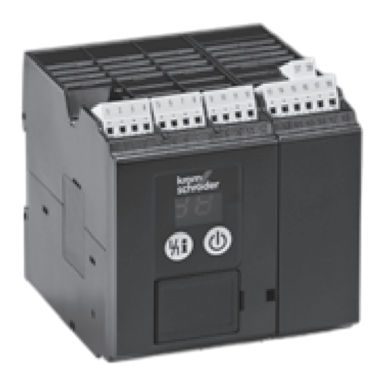
Part designations Checking the usage Burner control units BCU 560, 565 and 580 are designed to monitor and control gas burners in in- termittent or continuous operation. The outputs for controlling the burners, e.g. for fan, actuator and valves, are activated via a replaceable power module. -
Page 3: Installation
Installation Replacing the power module/ parameter chip card CAUTION 1 Disconnect the unit from the electrical power Please observe the following to ensure that the supply. burner control unit is not damaged: – Dropping the device can cause permanent dam- age. -
Page 4: Chip Card
Cable selection Wiring ▷ Signal and control line for screw terminals max. ▷ Do not reverse phase L1 and neutral conduc- 2.5 mm (min. AWG 24, max. AWG 12), for spring tor N. ▷ Do not connect different phases of a three-phase force terminals max. 1.5 mm (min. AWG 24, max. AWG 12). -
Page 5: Connection Diagram
▷ Legend – see page 25 (Legend). Connection diagram BCU 560..F0 GB-5... - Page 6 BCU 560..F ▷ Legend – see page 25 (Legend). GB-6...
- Page 7 BCU 565..F ▷ Legend – see page 25 (Legend). GB-7...
- Page 8 BCU 580..F ▷ Legend – see page 25 (Legend). GB-8...
- Page 9 IC 0 connected to BCU..F1 ▷ Parameter 40 = 1. ▷ Continuous control via three-point step controller. F1:T3,15AH BCU..F1 F2:T2AH 12 11 3 2 1 GB-9...
- Page 10 IC 0..E connected to BCU..F1 ▷ Parameter 40 = 1. ▷ Continuous control via an analogue signal (di- rectly connected to the control actuator). F1:T3,15AH BCU..F1 F2:T2AH 20 19 18 12 11 3 2 1 S 1 0 1 2 3 4 5 6 µC GB-10...
- Page 11 IC 40 connected to BCU..F1 ▷ Parameter 40 = 2. ▷ Set IC 40 to operating mode 27, see operating instructions Actuators IC 20, IC 40, IC 40S. F1:T3,15AH BCU..F1 F2:T2AH 22 21 20 19 18 16 15 14 12 11 10 GB-11...
- Page 12 RBW valve connected to BCU..F ▷ Parameter 40 = 3. Continuous control via three-point step controller F1:T3,15AH BCU..F2 F2:T2AH R B W 0° 90° 90° 0° Continuous control via PLC F1:T3,15AH BCU..F2 F2:T2AH + F - 0°➔90° GB-12...
-
Page 13: Flame Control
Flame control BCU 580 ▷ BCU 560, 565 = 1 flame amplifier Pilot burner = single-electrode operation/ ▷ BCU 580 = 2 flame amplifiers main burner = ionization: ▷ In the case of UV control, use Elster UV sensors ▷ Pilot burner in single-electrode operation for intermittent operation (UVS 1, 5, 6, 10) or ▷... -
Page 14: Adjustment
▷ If the password has been changed, the end cus- Pilot burner = UVC/main burner = UVC: ▷ Parameter 04 = 6 tomer can look up the changed password in the plant documentation or ask the system supplier. Commissioning ▷ During operation, the 7-segment display shows the program status: 00 Standby UVC 1... -
Page 15: Manual Mode
▷ Manual mode is terminated by switching off the BCU 560..F0 Apply the start-up signal to terminal 1. BCU or in the event of a power failure. ▷ The display indicates ▷ Parameter 67 = 0: Manual mode unlimited in ▷... -
Page 16: Assistance In The Event Of Malfunction
! Ignition cable has no contact in the ignition trans- Assistance in the event of former. malfunction • Check the connection. ! Ignition cable has short-circuited to ground. DANGER • Check installation, clean the spark electrode. • If the fault cannot be remedied by doing this, Electric shocks can be fatal! Before working on remove the unit and return it to the manufacturer possible live components, ensure the unit is discon-... - Page 17 ? The display blinks and indicates or ? The display blinks and indicates The BCU has detected an incorrect flame sig- Actuation of the remote reset input is faulty. nal without burner 2 (main burner) having been Too many remote resets. More than 5 resets ignited (extraneous signal).
- Page 18 • If the measures described above do not help, remove the unit and return it to the manufacturer for inspection. ? The display blinks and indicates ! Inputs 51 and 52 are activated simultaneously. • Check input 51. ▷ Input 51 may only be activated if the valve is open. ? The display blinks and indicates •...
- Page 19 • Change parameter 56 (Measurement time V using BCSoft. • If the fault cannot be remedied by doing this, remove the unit and return it to the manufacturer ? The display blinks and indicates for inspection. ! The bus module and control unit are incompat- ible.
- Page 20 • Check the wiring. ? The display blinks and indicates ! Faulty valve actuation, reversed valve connection. • Check the wiring of the solenoid valves. ? The display blinks and indicates ! Faulty actuation of the input at terminal 44. The BCU is prompted to go into menox mode, even though there is no signal for high temperature operation (> 750°C) at terminal 49.
- Page 21 • If the measures described above do not help, the unit has probably suffered a hardware defect – remove the unit and return it to the manufacturer for inspection. ? The display blinks and indicates ? The display blinks and indicates ! The input signal for the air pressure switch has ! The “no flow”...
- Page 22 ! One of the external flame detectors detects an extraneous signal (an incorrect flame signal). • Eliminate extraneous signal. ! Incorrect voltage supply to terminal 67. ? The display blinks and indicates • Check voltage supply to terminal 67. ! Internal communication with bus module has ! Parameter 45 has been set incorrectly.
-
Page 23: Reading Off The Flame Signal, Fault Messages And The Parameters
• Press the Reset/Information button again for 2 s to go to the next item of information (fault message, parameter value). ▷ Each time the button is released, the correspond- ? The display blinks and indicates ing fault message or parameter value is displayed. ! The bus module has received an incorrect con- ▷... - Page 24 Parameter name Parameter name ram- ram- eter eter Parameter value Parameter value Low air pressure protection Valve proving system 0 = Off 0 = Off 1 = With safety shut-down 1 = Tightness test before start-up 2 = With fault lock-out 2 = Tightness test after shut-down Delayed low air pressure protection 3 = Tightness test before start-up and after shut-down...
-
Page 25: Legend
Legend Parameter name ram- eter Parameter value Ready for operation Function of terminal 67 Safety interlocks (limits) 0 = Off 8 = AND gating with emergency stop input High temperature operation (terminal 46) 9 = AND gating with air pressure switch input Gas valve (terminal 47) Air valve... -
Page 26: Technical Data
Mechanical data Technical data Weight: 0.7 kg. Electrical data Dimensions (W × H × D): 102 × 115 × 112 mm. Mains voltage: Connections: BCU..Q: 120 V AC, -15/+10%, 50/60 Hz, ±5%, Screw terminals: BCU..W: 230 V AC, -15/+10%, 50/60 Hz, ±5%, nominal cross-section 2.5 mm², for grounded mains. -
Page 27: Logistics
Connection plug set Logistics For wiring the BCU. Transport Protect the unit from external forces (blows, shocks, vibration). On receipt of the product, check that the delivery is complete, see page 2 (Part designa- tions). Report any transport damage immediately. 74923998 74924000 Storage... -
Page 28: Certification
SIL, PL Certification Declaration of conformity For systems up to SIL 3 pursuant to EN 61508. Pursuant to EN ISO 13849-1, Table 4, the BCU can We, the manufacturer, hereby declare that the prod- be used up to PL e. ucts BCU 560, BCU 565 and BCU 580 comply with FM approved the essential requirements of the following Directives...
Need help?
Do you have a question about the BCU 56 Series and is the answer not in the manual?
Questions and answers