Sign In
Upload
Manuals
Brands
krom schroeder Manuals
Control Unit
MPT 700
krom schroeder MPT 700 Manuals
Manuals and User Guides for krom schroeder MPT 700. We have
1
krom schroeder MPT 700 manual available for free PDF download: Manual
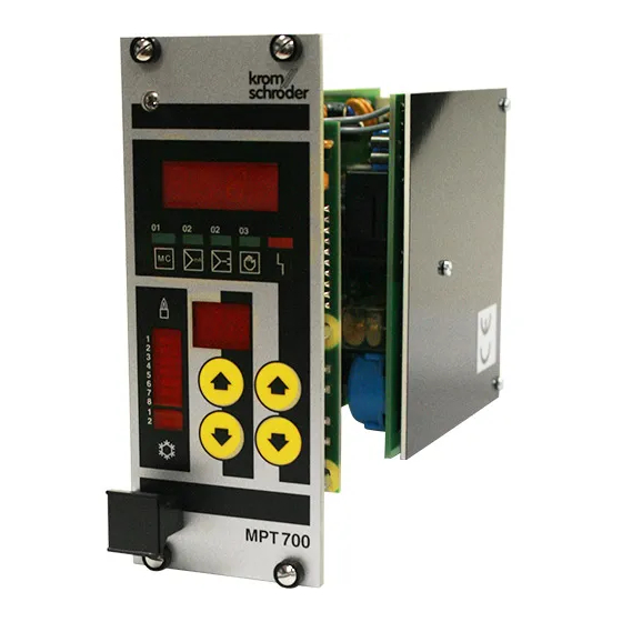
krom schroeder MPT 700 Manual (59 pages)
Impulse system
Brand:
krom schroeder
| Category:
Control Unit
| Size: 0 MB
Table of Contents
Table of Contents
2
1 Introduction
4
Version and Model
5
CE Mark
7
2 Operation
8
Controls
8
Front Panel
8
Parameter Display
9
Group Indicator
9
Setting Source Indicators
9
Malfunction Indicator
10
Switching Output Indicators
10
Keypad
10
Operation of the Unit
11
General
11
Parameters 0
11
Parameter Entry - General
11
3 Modes of Operation
13
Mode of Operation 1 - Heating with Fixed Pulse Width
13
Mode of Operation 2 - Heating/Cooling with Fixed Pulse Width
14
Mode of Operation 3 - Heating with Variable Pulse Width and Spacing
16
Mode of Operation 4 - Heating/Cooling with Variable Pulse Width and Spacing
18
Mode of Operation 5 - Heating with Fixed Pulse Width and Separate Air and Gas Valve Control
21
Mode of Operation 6 - Heating/Cooling with Fixed Pulse Width and Separate Air and Gas Valve Control
23
Mode of Operation 7- Heating with Variable Pulse Width and Spacing and Separate Air and Gas Valve Control
25
Mode of Operation 8 - Heating/Cooling with Variable Pulse Width and Spacing and Separate Air and Gas Valve Control
28
4 Adjustable Parameters 10
31
Parameter 10 - Setting Source
31
Parameter 11 - Mode of Operation
32
Parameter 12, 13 - Equipment Address
32
Parameter 14 - Setting Indicator
32
Parameters 15, 16 - Number of Outputs
32
Parameter 18 - MPT Mode
33
Parameter 19 - Keyboard Repetition Rate
33
Parameters 20
33
Parameter 28, 29 - Setting Control Factor
35
Parameter 30, 31 - Heating/Cooling Limit
35
Parameter 32, 33 - Heating/Cooling Dead Zone
35
Parameter 34, 35 - Continuous Pulse
37
Parameter 36, 37 - Control Rate (Three-Point Step Controller)
37
Parameter 38, 39 - Fixed Setting
38
Parameters 40
38
Parameters 48, 54, 68, 74 - Minimum on Time
39
Parameters 49, 55, 69, 75 - Minimum off Time
39
Parameters 50
39
Parameter 87 - Equipment Code
40
5 Appendix
41
Installation
41
Proper Use
41
Installation Notes and Safety Precautions
41
General
42
Ground Connection
43
Power Supply Connections
43
Binary Control Inputs
44
Ma Control Inputs
44
Switching Outputs
45
Connection Plans
46
Main Board
46
Power Supply Board
47
Jumpers (on Main Board)
48
Fuses (on Power Supply Board)
48
Block Diagram (Overview)
49
Terminal Plan (CN1)
50
Brief Instructions
51
Modes of Operation
51
Parameter 10 - Setting Source
51
Parameters 0
52
Test and Service Instructions
53
Parameter 5: Test Ma Control Input/Phase
54
Parameter 6: Test of Binary Control Inputs
54
Parameter 7: Test of Switching Outputs
55
Parameter 8: Error Parameter Number
55
Parameter 9: Error Code
56
Parameters 90
57
Parameter 99: Display Test
57
Cold Start
57
Connections
57
Technical Specifications
58
Advertisement
Advertisement
Related Products
krom schroeder BCU 46 Series
krom schroeder BCU 480
krom schroeder BCU 56 Series
krom schroeder BCU 570
krom schroeder BCU 580
krom schroeder IFD 244
krom schroeder IFD 258
krom schroeder OCU
krom schroeder Categories
Control Unit
Controller
Switch
Security Sensors
Burner
More krom schroeder Manuals
Login
Sign In
OR
Sign in with Facebook
Sign in with Google
Upload manual
Upload from disk
Upload from URL