Table of Contents
Advertisement
057
D
GB
F
NL
I
TR
CZ
PL
RUS
H
Operating instructions
Cert. version 02.18
Contents
Contents
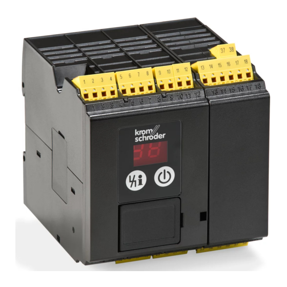
Burner control unit BCU 570. . . . . . . . . . . . . .
Contents . . . . . . . . . . . . . . . . . . . . . . . . . . . . . .
Safety. . . . . . . . . . . . . . . . . . . . . . . . . . . . . . . . .
Checking the usage . . . . . . . . . . . . . . . . . . . . .
Installation . . . . . . . . . . . . . . . . . . . . . . . . . . . .
Replacing the power module/parameter
chip card . . . . . . . . . . . . . . . . . . . . . . . . . . . . . .
Cable selection. . . . . . . . . . . . . . . . . . . . . . . . . 4
Wiring . . . . . . . . . . . . . . . . . . . . . . . . . . . . . . . . 4
Connection diagram . . . . . . . . . . . . . . . . . . . . 5
BCU 570 . . . . . . . . . . . . . . . . . . . . . . . . . . . . . . 5
Flame control . . . . . . . . . . . . . . . . . . . . . . . . . . . 6
IC 20 connected to BCU 570..F1. . . . . . . . . . . . 7
IC 20..E connected to BCU 570..F1 . . . . . . . . . 8
IC 40 connected to BCU 570..F1. . . . . . . . . . . . 9
RBW valve connected to BCU 570..F2 . . . . . . 10
F2 . . . . . . . . . . . . . . . . . . . . . . . . . . . . . . . . . . 11
Adjustment . . . . . . . . . . . . . . . . . . . . . . . . . . .
Commissioning. . . . . . . . . . . . . . . . . . . . . . . .
Manual mode . . . . . . . . . . . . . . . . . . . . . . . . .
Assistance in the event of malfunction . . . .
Replacing the fuse . . . . . . . . . . . . . . . . . . . . . . 18
messages and the parameters. . . . . . . . . . . 9
Parameters and values. . . . . . . . . . . . . . . . . . . 19
Legend. . . . . . . . . . . . . . . . . . . . . . . . . . . . . . .
Technical data . . . . . . . . . . . . . . . . . . . . . . . .
Designed lifetime . . . . . . . . . . . . . . . . . . . . . . . 22
Logistics . . . . . . . . . . . . . . . . . . . . . . . . . . . . .
E
DK
S
N
P
GR
www.docuthek.com
Safety
Safety
Please read and keep in a safe place
Please read through these instructions
carefully before installing or operating. Following the
installation, pass the instructions on to the opera-
tor. This unit must be installed and commissioned
in accordance with the regulations and standards
in force. These instructions can also be found at
www.docuthek.com.
Explanation of symbols
• , , , ... = Action
▷
= Instruction
Liability
We will not be held liable for damage resulting from
non-observance of the instructions and non-com-
pliant use.
Safety instructions
Information that is relevant for safety is indicated in
the instructions as follows:
DANGER
Indicates potentially fatal situations.
WARNING
Indicates possible danger to life and limb.
CAUTION
Indicates possible material damage.
All interventions may only be carried out by qualified
gas technicians. Electrical interventions may only be
carried out by qualified electricians.
Conversion, spare parts
All technical changes are prohibited. Only use OEM
spare parts.
Changes to edition 0.5
The following chapters have been changed:
-
Installation
-
Connection diagram
-
Commissioning
-
Assistance in the event of malfunction
-
Certification
GB-1
Advertisement
Table of Contents

Related Manuals for krom schroeder BCU 570


Summary of Contents for krom schroeder BCU 570
-
Page 1: Table Of Contents
All technical changes are prohibited. Only use OEM BCU 570 ......5 spare parts. -
Page 2: Checking The Usage
Input voltage – see type label. Checking the usage Burner control unit BCU 570 is designed to moni- tor and control modulating forced draught burners of unlimited capacity in intermittent or continuous operation. The fail-safe outputs for controlling the burners, e.g. for fan, actuator and valves, are activated via a re- placeable power module. -
Page 3: Installation
Installation Replacing the power module/ parameter chip card CAUTION Disconnect the system from the electrical power Please observe the following to ensure that the supply. burner control unit is not damaged: – Dropping the device can cause permanent dam- age. -
Page 4: Cable Selection
Cable selection Wiring ▷ Signal and control line for screw terminals max. ▷ Do not reverse phase L1 and neutral conduc- 2.5 mm (min. AWG 24, max. AWG 12), for spring tor N. ▷ Do not connect different phases of a three-phase force terminals max. 1.5 mm (min. AWG 24, max. AWG 12). -
Page 5: Connection Diagram
▷ Legend – see page 21 (Legend). Connection diagram BCU 570 GB-5... -
Page 6: Flame Control
Flame control ▷ In the case of UV control, use Elster UV sensors for intermittent operation (UVS 1, 5, 6, 10) or flame detectors for continuous operation (UVC 1). Ionization/single-electrode operation: ▷ Parameter 04 = 0. UV control: UVS 1, 5, 6, 10 ▷... -
Page 7: Ic 20 Connected To Bcu 570
IC 0 connected to BCU 570..F ▷ Parameter 40 = 1. ▷ Continuous control via three-point step controller. BCU 570 3.15AT 3,15AT 12 11 3 2 1 GB-7... -
Page 8: Ic 20
IC 0..E connected to BCU 570..F ▷ Parameter 40 = 1. ▷ Continuous control via an analogue signal (di- rectly connected to the control actuator). BCU 570 3.15AT 3,15AT 20 19 18 12 11 3 2 1 S 1 0 1 2 3 4 5 6 µC... -
Page 9: Ic 40 Connected To Bcu 570
IC 40 connected to BCU 570..F ▷ Parameter 40 = 2. ▷ Set IC 40 to operating mode 27, see operating instructions Actuators IC 20, IC 40, IC 40S. BCU 570 3,15AT 3.15AT 22 21 20 19 18 16 15 14 12 11 10... -
Page 10: Rbw Valve Connected To Bcu 570
RBW valve connected to BCU 570..F ▷ Parameter 40 = 3. Continuous control via three-point step controller BCU 570 3,15AT 3.15AT R B W 0° 90° 90° 0° Continuous control via PLC BCU 570 3,15AT + F - 0° 90° GB-10... -
Page 11: Frequency Converter Connected To Bcu 570
Frequency converter connected to BCU 570..F ▷ Parameter 40 = 4. BCU 570 3.15AT 3,15AT Target = actual DI 1 DI 2 DI 3 0–100% GB-11... -
Page 12: Adjustment
Switch on the system. Adjustment ▷ The display indicates –– In certain cases, it may be necessary to change the Switch on the BCU by pressing the On/Off but- parameters set at the factory. Using the separate ton. software package BCSoft and a PC opto-adapter, it ▷... -
Page 13: Assistance In The Event Of Malfunction
? Start-up without flame – no ignition spark – dots disappear. the display blinks and indicates ! The ignition cable is too long. BCU 570..F with IC 40, BCU 570..F with • Shorten it to 1 m (max. 5 m). RBW or frequency converter ▷ Following controller enable (status display ... - Page 14 ? The display blinks and indicates ! Actuation of the remote reset input is faulty. ! Too many remote resets. More than 5 resets have been conducted within the last 15 minutes, ? Start-up – flame burning – nevertheless, the either automatically or manually. display blinks and indicates or ...
- Page 15 • Establish the cause of the fault to avoid repeat faults. • Ensure that the cables have been installed prop- erly – see page 4 (Cable selection). ? The display blinks and indicates • If the measures described above do not help, ! Actuator IC 20 has been wired incorrectly.
- Page 16 ? The display blinks and indicates ? The display blinks and indicates ! One of the burner-side gas solenoid valves is ! The time between two starts is less than the leaking. min. time (timing cycle). • Check the burner-side solenoid valves. •...
- Page 17 • If the measures described above do not help, the • Check the air supply. unit has probably suffered a hardware defect – • Check the air pressure switch setpoint. remove the unit and return it to the manufacturer for inspection. ? The display blinks and indicates ...
-
Page 18: Replacing The Fuse
▷ Device name on delivery: not-assigned-bcu-570-xxx (xxx = code switch setting on the BCU). ▷ The device name must at least consist of the expression bcu-570-xxx. • Check whether the code switch setting is identi- cal to the entry (xxx) in the PLC program. •... -
Page 19: Reading Off The Flame Signal, Fault Messages And The Parameters
• If the fault cannot be remedied by doing this, Reading off the flame signal, fault remove the unit and return it to the manufacturer messages and the parameters for inspection. ▷ During operation (display ), information about the flame signal intensity, the last 10 fault mes- sages and the parameter values can be read off by repeatedly pressing the Reset/Informa- tion button. - Page 20 Name Name ram- ram- Values Values eter eter High gas pressure protection Function of terminal 51 0 = Off 0 = Off 1 = With fault lock-out 8 = AND with emergency stop (trm. 46) 2 = With safety shut-down 9 = AND with air min. (trm. 47) Low gas pressure protection 10 = AND with air flow monitoring (trm. 48) 0 = Off...
-
Page 21: Legend
Legend Name ram- Values eter Ready for operation Pilot burner operation 0 = With shut-down Safety interlocks (limits) 1 = Continuous operation Fieldbus communication High temperature operation 0 = Off Gas valve 1 = With address check 2 = No address check Air valve Pre-ignition time 0 –... -
Page 22: Technical Data
Connections: Technical data Screw terminals: Electrical data nominal cross-section 2.5 mm², Mains voltage: wire cross-section (rigid) min. 0.2 mm², BCU 570Q: 120 V AC, -15/+10%, 50/60 Hz, ±5%, wire cross-section (rigid) max. 2.5 mm², BCU 570W: 230 V AC, -15/+10%, 50/60 Hz, wire cross-section AWG/kcmil min. 24, ±5%, wire cross-section AWG/kcmil max. 12. - Page 23 For printing with laser printers, plotters or engraving We, the manufacturer, hereby declare that the product machines, 27 × 18 mm or 28 × 17.5 mm. BCU 570 complies with the requirements of the listed Colour: silver. Directives and Standards. Connection terminal set Directives: For wiring the BCU.
- Page 24 UL listed Underwriters Laboratories – UL 372 Standard for Limit Controls Eurasian Customs Union The product BCU 570 meets the technical specifica- tions of the Eurasian Customs Union. Registered design U.S. Patent No. D682,794 Directive on the restriction of the use of hazardous substances (RoHS) in China Scan of the Disclosure Table China RoHS2 –...
Need help?
Do you have a question about the BCU 570 and is the answer not in the manual?
Questions and answers