Advertisement
Quick Links
Advertisement

Related Manuals for Triple Plus CLM


Summary of Contents for Triple Plus CLM
- Page 1 Triple CLM Installation & Operation Manual...
- Page 2 Leak management and damage prevention...
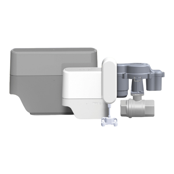
- Page 3 Thank you for choosing the Triple+ CLM™ Cloud-based Leak Management system designed to detect water leaks and prevent the subsequent damages. Triple+ CLM™ system will give you peace of mind while at home and away. Triple+ CLM™ line of products is the most comprehensive leak management and damage prevention solution in the market.
- Page 4 App offers a true remote management regardless of being home or away. The Triple+ CLM™ system is fully resilient to any Internet communication failure and will work in its autonomous offline mode, providing a complete protection of the premises against water leak damages.
-
Page 6: General Info
General Info Warnings This product was designed to prevent water leak damages and as such should be used for water piping only. Please read through the instructions carefully and follow the steps of the system’s installation. Please maintain this document in a safe place for future reference. When in any doubt, contact your authorized distributor or installer. - Page 7 System component pairing and positioning system is installed by a certiied professional installer and Triple+ CLM™ activated using the mobile installer’s App. Please look for Triple+ CLM™ Installer App in Google Play for Android OS-based smartphones or in the App Store for iOS devices.
- Page 8 LAN (local area network), in a wireless-only LAN (WLAN), or in a mixed wired/wireless network, depending on the need. Once paired by the professional installer using the Triple+ CLM™ Installer’s App, the HUB is ready for action. The HUB allows understanding of devices’ state...
- Page 9 HUB description Power cable. Table mount bracket. Lower cover. HUB circuit body RGB LED indicator. Wall mounting bracket (on the rear part)
- Page 10 HUB installation When interested in HUB wall mounting, please follow the following instructions: 1. Detach the HUB from the table stand 2. Attach the wall mounting bracket to intended as described below. location and mark the holes for the mounting screws. 3.
- Page 11 Expected HUB LED behavior Faultless communication of the HUB with all the components and with the server : The HUB RGB LED will repeatedly blink in GREEN every 5 seconds. Failure in communication with the server or with any of the system components: The HUB RGB LED will repeatedly blink in BLUE...
- Page 12 Flood Detector Setup Triple+ CLM™ flood detectors are to be installed in places probe to water floods or leaks. When a puddle of water is detected, wireless signal is dispatched to initiate closure of the shutoff unit(s) and push notiications is sent to the End User’s App.
- Page 13 Flood Detector description 1_Indication LED 2_Water detector 3_Battery housing cover 4_Wall mount bracket 5_Double-sided adhesive tape application locations (rear)
- Page 14 Flood Detector installation 1. Open the battery 2. Remove 3. Install 2 AAA housing cover the cover and batteries in the by pulling it expose the battery housing, towards the cable, battery housing. please note while holding the the polarity detector body.
- Page 15 Expected Flood Detector LED behavior GREEN blink once in 30 seconds – all is OK once in 30 seconds – communication problems RED blink RED blink once in 10 seconds – ongoing water leak once in 30 seconds – low lood detector battery BLUE blink Flood Detector installation limitations Places where the detector should not be installed or positioned at:...
- Page 16 Integrated Shutoff Setup The Integrated ¾”-pipe diameter compatible Shutoff unit is installed on the main water supply pipe within the premises (or outdoors, in a water tight plastic casing) and controls the water flow within the pipeline. When needed, using standard plumbing adapters, the unit can interface various pipe diameters.
- Page 17 Integrated Shutoff unit description 1_Closing/ opening handle. 2_Close/ open dial. 3_Disconnection unit (valve) body. 4_Battery cover 5_Entry/ exit 3/4” adapter. 6_Base for non-wall mounted valve 7_Base for wall mounted valve.
- Page 18 Integrated Shutoff unit installation Installation and/or replacement of a battery should be performed by authorized personnel. The system should not disconnect a ire extinguishing line or a ire sprinkler line. Locate the most suitable place for installation on the water line (as indicated above.) Shut down the water supply, using the main valve of the building or site.
- Page 20 Triple+ CLM™ Actuator Shutoff Unit The wireless, battery operated water and gas Shutoff unit is installed on any ISO5211 valve. It will actuate whenever a risky event is identiied or when manually requested by the user. This actuator is mounted on a ISO5211 flange using 2 screws, provided with the installation kit.
- Page 21 Actuator Shutoff unit description F_Top part of the case A_Shutoff unit motor G_Screw tunnel B_Bottom part of the case H_Battery housing C_Motor stem position windows I_Mounting itting D_Indication RGB LED J_Lock E_Multipurpose button K_Battery housing cover* *Just in the version 2 of the Shutoff unit...
- Page 22 Actuator Shutoff unit Warnings The system should not disconnect a ire extinguishing line or a ire sprinkler line. Ensure easy access shut off unit in case it might be required for service. The unit can be installed perpendicularly or in parallel with the pipe. With the utilization of the locking pin, a comfortable shutoff disconnection should be possible after installation.
- Page 23 Shutoff unit setup and mounting Locate the most suitable place for installation on the water line. Shut down the water supply, using the main valve of the building or site. Parallel Shutoff unit Mount the neck assembly on the mounting shutoff and install it on ISO5211 mounting pad using the attached screws, washers and nuts.
- Page 24 Actuator Shutoff unit alignment reset The shutoff unit alignment reset is necessary in order to indicate the CLM™ HUB that the unit is in the “CLOSED” position and thus prevents the water from passing through the pipe. 1. Regardless of the shutoff mounting, whether parallel or perpendicular to the water flow direction, align the slot on the top part of the shutoff motor stem perpendicularly to the water flow direction.
- Page 25 Expected Actuator Shutoff unit LED behavior In order to save the shutoff unit battery, the LED indicator is not active, unless the unit button is momentarily pressed. The activity time frame of the LED indicator is 30 seconds. Faultless communication of the HUB with all the components and with the server: The SHUTOFF UNIT LED will repeatedly blink in GREEN every 5 seconds (see...
-
Page 26: Fcc And Industry Canada Compliance Statement
FCC and Industry Canada Compliance Statement This device complies with FCC Rules Part 15 and with Industry Canada license-exempt RSS standard(s). Operation is subject to two conditions: (1) This device may not cause harmful interference, and (2) this device must accept any interference that may be received or that may cause undesired operation. - Page 27 FCC and Industry Canada Compliance Statement Le présent appareil est conforme aux CNR d’Industrie Canada applicables aux appareils radio exempts de licence. L’exploitation est autorisée aux deux conditions suivantes : (1) l’appareil ne doit pas produire de brouillage, et (2) l’utilisateur de l’appareil doit accepter tout brouillage radioélectrique subi, même si le brouillage est susceptible d’en compromettre le fonctionnement.
- Page 28 Triple+ Ltd. | 5 Hamada St., High Tech Park, Yoqneam, 2069200, Israel +972-(0)72-2211370 | info@tripleplus.io | www.tripleplus.io...
Need help?
Do you have a question about the CLM and is the answer not in the manual?
Questions and answers