Table of Contents
Advertisement
Quick Links
Welcome
Thank you for choosing Triple+ CLM™ (Cloud Leak Management) system
designed to detect Water leaks and prevent the subsequent damages. The
Triple+ CLM™ system will give you peace of mind while at home and out of
it.
Please note
Please read through the instructions carefully and follow the steps of the
system's installation and commissioning.
Please maintain this document in a safe place for future reference. When in
any doubt, contact your authorized distributor or installer.
Triple+ CLM™ system
TM
The Triple+ CLM
system detects and prevents water leaks. When the leak
is detected, the system disconnects the water supply wirelessly by activating
the shutoff units. Each installation can include multiple various detectors
and shutoff units installed on water pipe.
The system is designed to minimize potential flooding damages by shutting
down the water supply when the site is inactive and/or when a flooding
indication is received.
In addition, the Shutoff can be deactivated manually throughout the End
User APP or physical activation of the shut off units. The system is designed
for internal use and should be installed by an authorized technician.
Controller technical specification:
Part No.
CLM‐COAMAP‐1‐02, CLM‐COEMEA‐1‐02
Product description
Triple+ CLM™ HUB easily, securely and reliably
communicates with the connected devices and
tracks message delivery, allowing the
understanding of devices' state. It is ready to take
action
Dimensions
25x68x131mm (1x2.68x5.16")
Weight
155gr (0.33Lbs)
Power supply
External Adaptor Input 110‐240 V AC
Operation voltage
5V
Operating RF
915 MHz
Transmission range
Open space ‐ up to 230m (750ft.)
When a wall is within the space ‐ up to 120m
(390ft.) To avoid damaging the wireless
communication, avoid installation within metal
cabinets.
Working Temperature
‐20 to +50
Certifications
FCC ID:2AFOICLMCTRL10
IC:20798‐CLMCTRL10
WiFi module disclaimer:
The HUB includes a WLAN Smart module (Murata LBWB1ZZYDZ‐740) with
the following certification information: FCC ID: VPYLBYD / IC ID:772C‐LBYD.
There have not been any changes to the WLAN Smart module and it is used
for communicating bidirectional data between the router and system's
elements.
Tripleplus Ltd. | 5 Hamada St., High Tech Park, Yoqneam, 2069200, Israel | +972‐(0)72‐2211370 | info@tripleplus.io | www.tripleplus.io
0
0
C (‐4 to +122
F)
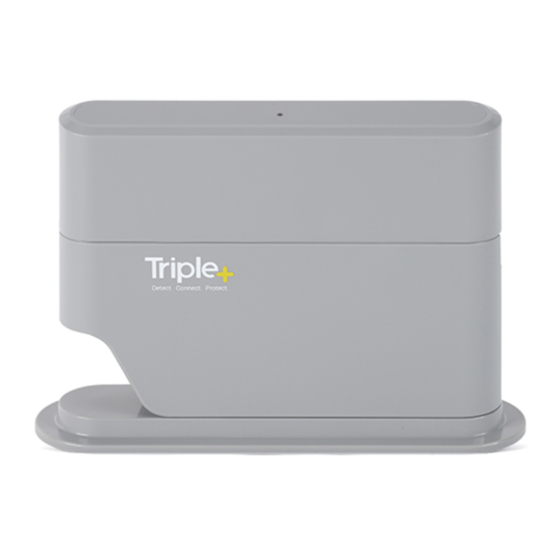
HUB description
A. Power cable.
B. Table mount bracket.
C. Lower cover.
D. HUB circuit body
E. USB connector.
F. RGB LED indicator.
G. Wall mounting bracket (on the rear part).
HUB installation
When interested in HUB wall mounting, please follow the following
instructions:
1.
Detach the HUB from the table stand as described below
2.
Attach the wall mounting bracket to intended location and mark
the holes for the mounting screws
Advertisement
Table of Contents

Summary of Contents for Triple Plus CLM-COAMAP-1-02
- Page 1 HUB description Welcome A. Power cable. Thank you for choosing Triple+ CLM™ (Cloud Leak Management) system B. Table mount bracket. designed to detect Water leaks and prevent the subsequent damages. The C. Lower cover. Triple+ CLM™ system will give you peace of mind while at home and out of D. HUB circuit body it. E. USB connector. Please note F. RGB LED indicator. Please read through the instructions carefully and follow the steps of the G. Wall mounting bracket (on the rear part). system's installation and commissioning. Please maintain this document in a safe place for future reference. When in ...
- Page 2 Connect the HUB to the AC/DC adaptor jack. Plug the LAN cable into the LAN inlet, if the HUB will be permanently operated via Expected HUB LED behavior the LAN. Normal functioning mode (when HUB operates on AC power): the HUB RGB LED should present the system statuses/alerts (as described below) repeatedly green blink every 5 seconds (see attached time diagram). Power saving mode (when HUB operates on its backup batteries): the HUB RGB LED should present the system statuses/alerts (as described below) once in 3 cycles (about 15 seconds) Maintenance mode (installation/reset): the HUB should present the maintenance status repeatedly LED colors mapping RGB LED Indication Alert/Status type Position the HUB on its permanent location. For wall mounting, GREEN BLUE RED bring the HUB’s rear mounting pins close to the wall and gently slide it down the wall mount’s dimples. Please do not attempt Faultless to rotate the HUB on the mounting in order to avoid physical communication of damage to the enclosure. the HUB with all Blinking the components and with the server Failure in communication with the server or Blinking ...


Need help?
Do you have a question about the CLM-COAMAP-1-02 and is the answer not in the manual?
Questions and answers