Table of Contents
Advertisement
Quick Links
SAFE 1/1.1
CM Manufactory GmbH
Otto-Hahn-Str. 3
D-72406 Bisingen
Tel. +49-(0)7476-9495-0
Fax. +49-(0)7476-9495-195
www.cm-manufactory.com
Zielgruppe/
Target audience
Zeichenerklärung/
Explanation of
signs
⇒
181204
Einleitung
Diese Betriebsanleitung soll Sie mit dem
Not-Halt Sicherheitsrelais und Schutztür-
wächter SAFE 1 / SAFE 1.1
vertraut machen.
Die Betriebsanleitung richtet sich an fol-
gende Personen:
Qualifizierte Fachkräfte, die Sicher-
heitseinrichtungen für Maschinen und
Anlagen planen und entwickeln und
mit den Vorschriften über Arbeitssi-
cherheit und Unfallverhütung vertraut
sind.
Qualifizierte Fachkräfte, die Sicher-
heitseinrichtungen in Maschinen und
Anlagen einbauen und in Betrieb
nehmen.
In dieser Betriebsanleitung werden einige
Symbole verwendet, um wichtige Infor-
mationen hervorzuheben:
Dieses Symbol steht vor Textstellen, die
unbedingt zu beachten sind. Nichtbeach-
tung führt zur Verletzung von Personen
oder zu Sachbeschädigung
Dieses Symbol kennzeichnet Textstellen,
die wichtige Informationen enthalten.
Dieses Zeichen kennzeichnet auszufüh-
rende Tätigkeiten
Nach diesem Zeichen wird beschrieben,
wie sich der Zustand nach einer ausge-
führten Tätigkeit ändert.
©
Copyright
Alle Rechte vorbehalten. Änderun-
gen, die dem technischen Fortschritt dienen, vor-
behalten.
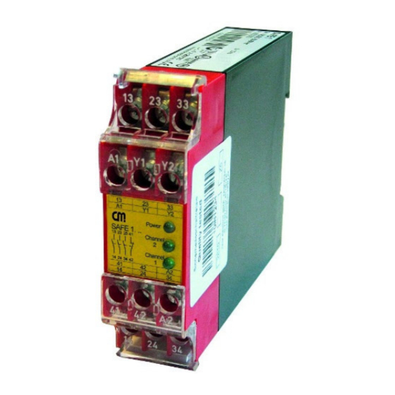
SAFE 1/1.1
13
23
33
A1
Y1 Y2
Original Betriebsanleitung
Safe 1
Sicherheitsschaltgerät für Not-Halt-
Power
13 23
33
41
Kreise und Schutztürüberwachungs-
Channel
2
kontakte
Channel
14 24
34 42
1
Original operating instructions
41
42 A2
Safety controller for e-stop and safety
14
24 34
gate monitoring applications
Introduction
This operating instruction should make
you familiar with the emergency stop and
safety gate monitoring relays
SAFE 1 / SAFE 1.1
The operating instruction is addressed to
the following persons:
Qualified professionals who plan and
develop safety equipment for ma-
chines and plants and who are famil-
iar with the safety instructions and
safety regulations.
Qualified professionals, who install
safety equipment into machines and
plants and put them into operation.
The operating instruction contains sev-
eral symbols which are used to high-light
important information:
This symbol is placed in front of text
which has to be absolutely paid attention
to. Nonobservance leads to serious inju-
ries or damage to property.
This symbol is placed in front of text,
which contains important information.
This sign is placed in front of activities
After this sign follows a description on
how the situation has changed after an
activity is performed.
©
Copyright
serve technical improvements are reserved.
All rights reserved. Changes, which
1
Advertisement
Table of Contents

Related Manuals for CM SAFE 1


Summary of Contents for CM SAFE 1
- Page 1 Diese Betriebsanleitung soll Sie mit dem This operating instruction should make Not-Halt Sicherheitsrelais und Schutztür- you familiar with the emergency stop and wächter SAFE 1 / SAFE 1.1 safety gate monitoring relays vertraut machen. SAFE 1 / SAFE 1.1 Die Betriebsanleitung richtet sich an fol-...
-
Page 2: Safety Indications
SAFE 1/1.1 Sicherheitshinweise Safety indications Bestimmungsgemäße Das Sicherheitsrelais SAFE 1 / SAFE 1.1 The safety relay SAFE 1 / SAFE 1.1 can Verwendung sind bestimmt für den Einsatz in: be used for: Ein-oder zweikanalige Schaltungs- Single-or dual channel capability for Application: technik für Not-Halt-Schalter... - Page 3 SAFE 1/1.1 Aufbau und Funktionsweise Assembly and function (function circuit diagram) Y1 Y2 13 23 33 elektr. Sicherung / electr. fuse Überwachungslogik / control logic 24 34 Ausgangskontakte: Output contacts: 13-14, 23-24, 33-34 Sicherheitsstrompfade (Schließer) safety circuits (normally open) 41-42 Signalisierungsstrompfad (Öffner)
-
Page 4: Montage Und Inbetriebnahme
SAFE 1/1.1 Mechanische Montage und Inbetriebnahme Mounting and opening Montage Für eine sichere Funktion muß das Si- The unit should be panel mounted in an mechanical cherheitsrelais in ein staub- und feuchtig- enclosure rated at IP 54 or better, other- mounting keitsgeschütztes Gehäuse eingebaut... - Page 5 SAFE 1/1.1 2. Eingangskreis schließen 2. Close input circuit Einkanalig: Schließen sie den Single-channel: Connect contact Kontakt des Auslöseelementes between trigger element to posi- zwischen die positive Versor- tive supply voltage and gungsspannung und A1(+) an A1(+). Zweikanalig: Schließen sie die Dual-channel: connect contact Kontakte des Auslöseelementes...
-
Page 6: Wartung Und Reparatur
Test the external wiring. keine LED brennt / Wenn Fehler immer noch vorhanden, When the fault is still available, send the Only one or no Gerät an CM Manufactory GmbH einschi- device to CM Manufactory GmbH. LED illuminates cken. 181204... -
Page 7: Technische Daten / Technical Data
SAFE 1/1.1 Technische Daten / Technical Data Elektrische Daten / electrical data Versorgungsspannung Uv / supply voltage 24V AC/DC Spannungsbereich voltage range 0,90 ...1,1 U Frequenz (AC-Variante) / frequency (AC-type) 50 ... 60 Hz Leistungsaufnahme ca. / power consumption appr. ca. 2,5 VA / 2,5 W... -
Page 8: Examples For Applications
Schütze zu einem beliebigen Zeitpunkt contactors can be operated or turned off bis Kategorie 2; SIL1; PLd dazugeschaltet bzw. abgeschaltet wer- at any time the SAFE 1... is activated. erreichbar den, wenn das SAFE 1... aktiviert ist. up to category 2; SIL1; PLd reachable Beispiel 3: Einkanalige Schutztürüber-... - Page 9 (mit getrennten mit der Gerätevariante SAFE 1 möglich. cally. Automatic start and automatic reset Mantelleitungen) is only possible using the SAFE 1 ver- sion. Gerätevarianten / Devices Spannung / Volt- Name / Name: Artikel-Nummer. / Article number:...
Need help?
Do you have a question about the SAFE 1 and is the answer not in the manual?
Questions and answers