
Related Manuals for Peter electronic VB 230-6 L


Summary of Contents for Peter electronic VB 230-6 L
- Page 1 e l e c t r o n i c Braking Devices VB 230/400-6/25/30L (LP) Assembly- and Commissioning Instructions Quality is our Drive.
-
Page 2: Table Of Contents
VB230/400-6/25/30L (LP) as per 06/19 1B000.10001 Table of Contents Page Safety notes Conformity General description Usage to the intended purpose EC Declaration of Conformity Block diagram Functional description (see connection diagram) LED indicators Fault signaling relay (only available with circuit-board version) Control inputs and outputs Control input Control outputs... - Page 3 VB230/400-6/25/30L (LP) These commissioning instructions were prepared with great care. Nevertheless, PETER electronic GmbH & Co. KG does not assume liability for damage resulting from mistakes possibly contained in this manual. Technical changes that serve to improve the product are subject to change without notice.
-
Page 4: Safety Notes
VB230/400-6/25/30L (LP) Safety notes The described devices are electrical equipment for use in industrial electrical power installations. An impermissible removal of the covers during operation can cause serious damage to your health, since these devices contain live parts with high voltages. -
Page 5: General Description
VB230/400-6/25/30L (LP) General description The electronic braking devices of the VersiBrake-L-type are available both as a housing version and as a circuit-board version (LP). They enable non-wearing braking of three-phase asynchronous motors and mono-phase motors. The braking devices are used for drives that, due to safety and functional reasons, have to be reliably slowed down. -
Page 6: Ec Declaration Of Conformity
(authorized representatives of the manufacturer / companies placing the product on the market that are established within the Community) Name / Address: PETER electronic GmbH & Co. KG Bruckäcker 9 92348 Berg hereby declares that the following product (device, component, unit) in the version as supplied... -
Page 7: Block Diagram
VB230/400-6/25/30L (LP) Block diagram (L1) (L2) (X1) (X2) Interlocking Current detection Controller Brems- (X10) relais Fault (X11) only available with circuit-board version (LP) (T1) (T2) (T3) Explanation: The designations for the housing variant are indicated without brackets, whereas those applicable for the circuit-board version are put into brackets. -
Page 8: Functional Description (See Connection Diagram)
VB230/400-6/25/30L (LP) Functional description (see connection diagram) After the operating voltage on 1L1 (L1) and 3L2 (L2) has been switched on, the main contactor interlock X5 (X5), X6 (X6) and, in the case of the circuit-board version, the fault signaling contact (X10), (X11) closes. -
Page 9: Led Indicators
VB230/400-6/25/30L (LP) LED indicators LED – ready (V9) Operational status - Illuminated - Mains voltage is applied, braking device is ready - Flashing 1x - No motor standstill detected during max. braking time - Flashing 2x - Adjusted braking current was not reached - Flashing 3x - Braking frequency too high - Flashing 5x... -
Page 10: Control Inputs And Outputs
VB230/400-6/25/30L (LP) Control inputs and outputs Control input Control terminals Designation Description X3 (X1), X4 (X2) Starting contact Connection of a normally closed contact of the motor contactor. In standard applications not required. Connection is only required, if more safety is required (redundant system) to initiate braking. -
Page 11: Control Outputs
VB230/400-6/25/30L (LP) Control outputs Control Designation Description terminals X5 (X5), X6 (X6), Interlock (potential- During braking, the contact between X5 and X6 is X7 (X7) free changeover open. This contact is to be looped into the control contact, common circuit of the motor contactor. Therefore, the motor contact on X5) cannot be started during braking. -
Page 12: Potentiometers
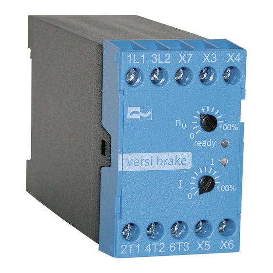
VB230/400-6/25/30L (LP) Potentiometers With the potentiometers it is possible to adjust the following parameters. The designations for the circuit-board version (LP) are indicated in brackets (). „I“, „(P2)“ Adjusting the braking current. The braking current can be adjusted in the range from approx. 10% - 100% of the rated device current. -
Page 13: Technical Data
VB230/400-6/25/30L (LP) 10. Technical data Type designation VB 230-6 VB 230- VB 230- VB 400-6 VB 400- VB 400- L (LP) 25 L (LP) 30 L (LP) L (LP) 25 L (LP) 30 L (LP) Mains voltage 220/240V ±10% 50/60Hz 380/415V ±10% 50/60Hz according to DIN EN 50160 (IEC 38) -
Page 14: Environmental Conditions
VB230/400-6/25/30L (LP) 10.1 Environmental conditions Storage temperature -25 ... 75°C Operating temperature 0 ... 45°C Degree of protection - Enclosed version (w. housing): IP 20 - Circuit-board version: IP 00 Environment Overvoltage category III, pollution degree 2 Weight - Enclosed version (w. housing): 0.6kg - Circuit-board version: 0.25kg... -
Page 15: Connection
VB230/400-6/25/30L (LP) 11.2 Connection The braking device is to be installed according to the attached connection diagram. For other connections please consult PETER electronic GmbH & Co. KG. Note: Further connection proposals for special circuit arrangements are available via our homepage at www.peter-electronic.com. - Page 16 VB230/400-6/25/30L (LP) Adjusting the braking time No adjustments are required, since the braking current is automatically switched off approx. 1.5s after a motor standstill has been detected. If no standstill is detected during the max. braking time (10s in the case of standard devices), the braking current is switched off when this time is over.
-
Page 17: Possible Fault Indications During Commissioning
VB230/400-6/25/30L (LP) 11.4 Possible fault indications during commissioning During commissioning, and in normal operation too, fault indications can occur. The following explanation is to give you assistance in the localization and correction of faults. Fault Fault Possible cause Fault correction indication on LED „Ready“, „(V9)“... -
Page 18: Dimensioning Rules
VB230/400-6/25/30L (LP) 12. Dimensioning rules Note! All data sheets and commissioning instructions are avaialble on our homepage at www.peter-electronic.com. 12.1 Dimensioning of braking contactors The braking contactor is switched on or off via a control contact of the braking device (no-load switching). - Page 19 On the basis of the recommended I²t-value, braking current, and possibly the c.d.f., the fuse supplier is able to select a suitable type. Due to the great variety of producers, sizes, and types, PETER electronic does not recommend any particular fuses.
-
Page 20: Permissible Braking Frequency
VB230/400-6/25/30L (LP) 12.3 Permissible braking frequency The braking frequency depends on the adjusted braking current. The braking devices of the VB …-25 L (LP) type allow the following braking frequencies: Braking current Braking time Braking frequency VB ...-6 L 1 braking operation per 8s 1 braking operation per 16s VB ...-6 L 1 braking operation per 5s... - Page 21 VB230/400-6/25/30L (LP) Table 3 Load curve for VB 400-6 L (LP) Cyclic duration factor in % --------------------------- - × Cyclicdurationfactor r · c · d · f · Cycletime = Braking time, Cycle time = Braking time + Non-braking time...
- Page 22 VB230/400-6/25/30L (LP) Load vurve for VB …-25 L (LP) Cyclic duration factor in % Load curve for BR 230/400-30L (LP) Cyclic duration factor in %...
-
Page 23: Dimensions
VB230/400-6/25/30L (LP) 13. Dimensions Enclosed version (with housing): Printed circuit-board version: All dimensions indicated in mm. -
Page 24: Typical Connections
VB230/400-6/25/30L (LP) 14. Typical connections 14.1 Connection diagram... - Page 25 VB230/400-6/25/30L (LP)
Need help?
Do you have a question about the VB 230-6 L and is the answer not in the manual?
Questions and answers