Table of Contents
Advertisement
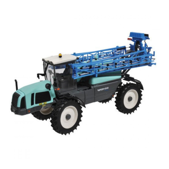
RAPTOR 2540-3240-4240-5240
Sprayer safety, checks and maintenance: see manual No. 82.471
NIVELEC / NIVOMATIC control box: see manual No. 82.494
* Speed limited at 33 km/h in Switzerland.
82.490 - Raptor
(E.C.T. = Regulation by pressure sensor)
82.490-C
To be read attentively
and kept for further reference
C-TRONIC regulation: see manual No. 82.510
Tables of NOZAL nozzles: see manual No. 82.467
DUALELEC control box: see manual No. 82.487
AXIALE II boom: see manual No. 82.486
AXIALE 36-38 boom: see manual No. 82.515
D.D.L. II boom: see manual No. 82.488
EKTAR B2 boom: see manual No. 82.513
EKTAR B3 boom: see manual No. 82.514
UC4 boom control system: see manual No. 82.506
UC5 boom control system: see manual No. 82.507
Follow-up of the E-Tech crops: see manual No. 82.519
regulation
ENGLISH
(40 km/h)*
© BERTHOUD Agricole 12/2015
1
Advertisement
Table of Contents


Need help?
Do you have a question about the RAPTOR 2540 and is the answer not in the manual?
Questions and answers